
User Manual


BRITECELL System Manual MN010-04 June 2003 Page 21 of 78
The company has a policy of continuous product development and improvement and we therefore
reserve the right to vary any information quoted without prior notice.
9.3. Up link operations
In uplink, signals pass through a duplexer and are then subjected to the following
operations:
O/E Conversion:
there are 4 O/E conversion devices (or optical receivers) in one TFL (one
for each optical link).
Amplification:
amplification is needed to compensate the optical fibre loss (maintaining a
good signal to noise ratio) so that for each link a constant gain is obtained.
RF Combining:
signals coming from all the remotes are combined into a single RF port.
Power level Adjustment:
TFL output may need a level adjustment so that the RF signals are within
the optimum BTS receiving range (please refer to TFL-BSI).
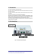
10. Alarms and settings
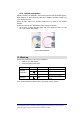
Two types of local alarm are available:
Visual alarms
:
the front panel of a TFL Local Unit shows the following status for alarm LEDs:
Link LED Colour Meaning (when lit)
= Green Laser is biased
Red
Laser optical power under limits
and/or bias is not present.
Downlink
Transmitter
OFF Yellow Laser has shutdown command.
Uplink receivers
Red
Input optical power is lower
than pre-set.
Tab. 2 -Alarm LEDs
Relay logic alarms detectable on connector:
in the rear of TFL units an alarm interface connector passes information about
summary alarms and specific alarms which can be sent to an OMC (Operating and
Maintenance Centre) via the BTS. In addition the alarms may be monitored from
Britecell’s own OMC (please refer to TPR).
Settings:
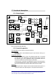
No adjustments are required at local interface module.
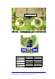
Four optical receivers are present at each TFL.
Unused receivers
may cause uplink alarms if enabled. In order to avoid UL alarms
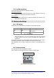
unused receivers must be turned off. This can be done simply changing jumper
position as shown on Fig. 9 and Fig. 10 .
Tab. 3 is a chart of the correct jumper positions.
Each receiver has a number silk screen printed on the metal protection, which
corresponds to the relevant UL optical port on the TFL front panel.
The jumper number and relevant receiver status are printed on TFA main board,
so that the operation results very simple.