
User Manual


BRITECELL System Manual MN010-04 June 2003 Page 20 of 78
The company has a policy of continuous product development and improvement and we therefore
reserve the right to vary any information quoted without prior notice.
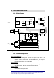
9. Functional description
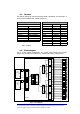
9.1. Block diagram
Fig. 8 - block diagram
9.2. Down link operations
In down link the TFL fulfils the following operations:
Power level adjustment:
if the RF signal coming from the BTS has a power level which is not
adequate to TFL’s characteristics, an external adjustment is required. It
consists in an attenuation when BTS is connected through a coupler or
through repeater (please refer to TFL-BSI).
E/O Conversion:
RF signal modulates the intensity of an optical carrier through an electro-
optic device (laser). One laser is present on each TFL card.
Optical Splitting:
modulated optical carrier is split into 4 ways so that it may be transmitted
on a maximum of 4 optical links.
RF IN
50 Ω
CURRENT
GENERATOR
NOISE
GENERATOR
Laser bias
Opt. power
monitor
IMPEDANCE
MATCHING
NETWORK
V
OPT
2-ways
combiner
+8V
VOLTAGE
REGULATOR
LASER module
MONITOR
PHOTODET.
LASER DIODE
STATUS MONITOR
LEDS AND ALARM
LEDS
ALARMS AND
COMMAD
CONNECTOR
VOLTAGE
REGULATOR
2-ways
combiner
VOLTAGE
CONTROLLED
ATTENUATOR
PHOTODETECTOR
LNA AMP AMP
TFLMICRO module
VARIABLE
GAIN AMP.
4 MHz
D
A
C
A
D
C
µPROC.
2-ways
combiner
RF OUT
50 Ω
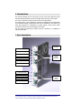
Optical
connectors
Pwr supply is
on
Pwr fault
TX
Low RX
opt.power
2-ways opt.
s
p
litter
Optical
connectors
POWER SUPPLY
U
NIT
+12V
Downlink Transmitter
ALARMS AND
COMMAND SIGNALS
MANAGEMENT
CIRCUITS
Uplink Receiver 1
Uplink Receiver 2
Uplink Receiver 3
Uplink Receiver 4
+5V
AC input from mains
2-ways opt.
s
p
litter
2-ways opt.
s
p
litter