SYSTEM INSTALLATION MANUAL Rel.
Copyright Tekmar Sistemi s.r.l. This document contains information, which is the property of Tekmar Sistemi S.r.l. The contents are confidential, any reproduction of all or part of this publication, without the written consent by Tekmar Sistemi s.r.l is forbidden. This publication is issued to provide outline information and is not deemed to form any part of any offer and contract.
1. INDEX 1. INDEX ....................................................................................................... 3 GENERAL INFORMATION ................................................................................... 6 2. HOW TO READ THIS MANUAL..................................................................... 7 3. INSTALLATION & SAFETY REQUIREMENTS.................................................. 8 3.1. Environmental conditions: ...............................................................
19.1. Location...................................................................................... 32 19.2. Power supply and grounding ........................................................ 32 19.3. RF combined ports ...................................................................... 33 19.4. Optical fibres connection.............................................................. 33 20. Start-up ................................................................................................. 33 21.
TPA antenna ................................................................................................... 55 54. Introduction ........................................................................................... 56 55. Functional description ............................................................................. 57 56. Installation and cabling ........................................................................... 58 56.1. Location.......................................................
GENERAL INFORMATION
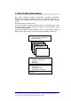
2. HOW TO READ THIS MANUAL This manual provides equipment specifications, operational descriptions, application, and installation information as well as a troubleshooting guide. It is intended to be a comprehensive document used to install and operate a Britecell system. The manual consists of many sections. The first main section includes a global description of the Britecell system, major equipment warnings, warranty information, customer service and support as well as troubleshooting guidelines.
3. INSTALLATION & SAFETY REQUIREMENTS 3.1. Environmental conditions: This equipment is designed to be installed inside buildings. Operating temperature: +5 to +40°C Do not install in corrosive atmosphere or in critical environmental conditions such as hazardous classified areas (for example see appendix C). 3.2. Installation site features A trained technician should carry out the installation of the donor rack.
3.3. Power connection Power connection has to be carried out following all the necessary precautions: • • • • • it must be properly made according to the due diligence rules (ex.: CEI rules, IEC rules, etc.); in accordance with the rules for safety against direct or indirect contacts; in accordance with the rules for safety against the over current (short circuit, overloading); in accordance with the rules for safety against over tension; connection is to be carried out by proper and competent staff 3.
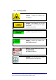
3.6. Warning Labels Caution! - invisible laser radiation from this aperture Caution! - Laser radiation. Do not stare into the beam or view directly with optical instruments – CLASS 3A laser product Caution! - angled polished connector Caution! - invisible laser radiation from this aperture – angle polished connectors Caution! - possible invisible laser radiation, max. power 30mW, wavelength 1300nm, laser product CLASS III B GROUND - Use this terminal for a safety ground connection of the equipment.
BRITECELL SYSTEM
4. SYSTEM DESCRIPTION Britecell is a low power distribution system designed to provide indoor coverage for mobile communication networks. .The whole system is based on the fiberoptic transmission of multiple RF carriers from an optical donor unit interfacing to the BTSs (TFL) and an optical remote unit located in remote sites (TFA) near an antenna. The transmission of the uplink and downlink RF signals is attained by using bidirectional fiberoptic links.
4.1. Services The Britecell system can operate with single band or dual-band.
4.3. Functional description The basic system blocks are the fiber donor unit TFL (Local Unit) and the fiber remote unit TFA (Remote Unit). They are connected in both directions (uplink and downlink) through single mode optical fibre. The system has a built-in Automatic Gain Control (AGC), which automatically adjust the up link and down link gain in order to compensate for optical link loss1.
5. EQUIPMENT DESCRIPTION Britecell is a modular system. Many options and accessories are available, depending on the desired coverage area. The following is a list of main accessories, suitable for most applications. 5.1. Britecell™ subracks The Local Units are located inside a 19” 6HE sub-rack. From this rack, power is supplied for the all fibre donor units (TFL). Fig. 3 – 19” sub-rack Subrack can be supplied by a -48V DC or by universal mains (85-264VAC). See datasheets for further details.
5.3. Remote equipment Fig. 4 - TFA remote unit remote antenna Fig. 5 - TPAxxx - Fig. 6 - TFB - RF booster TFA is the optical to RF converter. TPA is the suggested indoor antenna family. TFB is the RF booster if needed to extend the coverage area. TFA can feed up to two antennas while TFB can be connected to one antenna. Detailed descriptions of these components are available in the sections below.
TFL local unit
6. Introduction This section describes the TFL (Local Unit). The TFL is the part of Britecell system that provides E/O downlink conversion and O/E uplink conversion of RF signal. The TFL is connected to remote TFA by means of two optical fibres. The system forms a star configuration. One fibre is dedicated to the transmission of the downlink signals received from BTS and re-transmitted to the mobile.
8. Warnings 9 CAUTION! do not remove or insert any module into TPR subrack, without prior switching power supply off. 8.1. Connectors care and cleaning Optical connectors for single mode fibers are designed for submicron tolerances. Such a connector has an optical section of only 9 µm diameter. The rules below must be carefully followed 9 Do not leave optical connectors open, as they will attract dirt. 9 Do not touch the connector tip.
9. Functional description 9.1. Block diagram Downlink Transmitter 2-ways opt. splitter LASER module Laser bias CURRENT GENERATOR LASER DIODE IMPEDANCE MATCHING NETWORK RF IN 50 Ω 2-ways opt. splitter Opt. power monitor NOISE GENERATOR MONITOR PHOTODET. 2-ways opt. splitter Optical connectors AC input from mains VOLTAGE REGULATOR ALARMS AND COMMAD CONNECTOR Pwr fault TX +8V ALARMS AND COMMAND SIGNALS MANAGEMENT CIRCUITS +12V POWER SUPPLY UNIT VOLTAGE REGULATOR Low RX opt.
9.3. Up link operations In uplink, signals pass through a duplexer and are then subjected to the following operations: O/E Conversion: there are 4 O/E conversion devices (or optical receivers) in one TFL (one for each optical link). Amplification: amplification is needed to compensate the optical fibre loss (maintaining a good signal to noise ratio) so that for each link a constant gain is obtained. RF Combining: signals coming from all the remotes are combined into a single RF port.
Uplink receiver enabling Jumpers Fig. 9- Uplink jumpers RX OFF RX ON Fig. 10- Uplink jumper positions Receiver RX No.1 RX No.2 RX No.3 RX No.4 Status ON OFF ON OFF ON OFF ON OFF Jumper position JP1 JP2 JP3 JP4 JP5 JP6 JP7 JP8 Tab. 3 - Jumper positions BRITECELL System Manual MN010-04 June 2003 Page 22 of 78 The company has a policy of continuous product development and improvement and we therefore reserve the right to vary any information quoted without prior notice.
11. Installing and cabling 11.1. TPR housing The TFL modules are contained in a 6 HE sub-rack (TPR family). The local interfaces cannot be placed next to each other. The TFL local interface cards may only be fitted in slots 1, 3, 5, 7, 9, and 11 of the sub-rack. Fig. 11 - Subrack slots Fig. 12– Dummy plug If any slots are unused the backplane connectors must be fitted with a dummy plug (provided) to avoid alarms being generated (see Fig.15).
11.4. Optical connections Optical connectors are designed to have proper alignment and mechanical support. When inserting an optical connector, take care to handle it smoothly enough so as not to damage the fibre. Fasten the fibre cable to the provided seating base by means of the included wrapper. Remove the dust cap only immediately before making connections. 9 Do not force or stretch the fibre pigtail with curve radius less than 5 cm. See Fig. 13 for optimal fibre cabling. WRONG OPTIMAL Fig.
13. Troubleshooting Correct alarm interpretation is very useful not only during the installation, but also during maintenance TFL laser failure: replace the faulty transmitter by replacing the TFL unit with a new one. RX alarm only: first go to the TFL site and check if optical connectors of TFL are properly cleaned. If the problem still exists, go to the TFA site (the TFA which yields also visual RX alarm at TFL). If the TFA shows a visual alarm, clean the downlink optical connector.
TFA remote unit
14. Introduction This section describes the TFA (Remote Unit). The TFA is part of the Britecell system and provides O/E downlink conversion and E/O uplink conversion. The TFA is connected to passive antennas, which transmit and receive from and to the mobiles. Each TFA is connected to a TFL through two optical fibres. This forms a star configuration. One fibre is dedicated to the reception of the downlink signals that the TFA receives from TFL, and re-transmits to mobile stations.
16. Warnings 16.1. Connector care and cleaning Do not leave connectors open. Unused optical connectors must always be covered with their caps. 9 Do not touch the connector tip. Clean it with proper tissue before inserting them into the sleeve. 9 If better cleaning is needed, use pure ethyl alcohol. Sleeves may be cleaned by injecting pure gas under pressure. 9 Do not attempt to insert connectors mechanically incompatible. This will result in severe damage.
17. Functional description 17.1. Block diagram External Booster alarms Paging RF SMA connector 50 Ω LNA PHOTODETECTOR VOLTAGE CONTROLLED ATTENUATOR AMP (note1) RX optical power monitor A D C VARIABLE GAIN AMP. AMP AMP AMP AMP DL final amplifier stage current monitor D A C µPROC. Attenuator control voltage 4 MHz DL final amplifier stage out of allowed range Low RX optical power AMP AMP Diff.
17.3. Up link operations. In the uplink the TFA performs the following functions: Filtering & Amplification: a filter delimits the uplink band and a low noise amplifier increases the signal level to minimise the noise figure of the link. E/O Conversion: the RF signal coming from the antennas modulates the intensity of an optical carrier through a laser. 18. Alarms and settings 18.1. LED alarms For TFA units only visual alarms are provided.
18.3. Setting uplink gain (PGR) To optimise system performances related to “blocking level” (refer to system design for further details), TFA units shall include an RF uplink attenuator to adjust the uplink gain (Pre-settable Gain Reduction – PGR). Up link gain setting can be easily executed removing the rear lid (see Fig. 17) and setting SW1 bits (see Fig. 18) according to Tab. 5. Fig. 17 – TFA PGR dip- switches Fig.
19. Installing and cabling 19.1. Location TFA units shall be installed as close as possible to the radiating antennas, so as to minimise coaxial cable length and reduce downlink power loss and uplink noise figure. However, the units should be installed no closer than 2.5 m to the closest mobiles approach to avoid blocking. If remote units need to be installed very close to where mobiles are, the internal variable attenuator should be used.
19.3. RF combined ports These ports should be directly connected to the radiating antennas through RF jumper cables. Unused RF output ports must be terminated with a dummy 50Ω load. Optional boosters (TFB family) also can be connected to one or both of the combined ports for additional RF downlink power. 19.4. Optical fibres connection Optical connectors need to have proper alignment and mechanical support.
21. Troubleshooting If an alarm LED is active, check the environmental conditions (operating temperature, supply range, etc.). If an alarm persists, it is essential to give a correct alarm interpretation is to solve the problem. The uplink laser is switched on only if downlink optical power is present. In case of any failure, the laser is switched off. By doing this, the unit sends information about its operating status to the TFL. If the TFA is alarmed, clean the downlink optical connector.
TPR 19" subrack