
User Manual


BRITECELL System Manual MN010-04 June 2003 Page 51 of 78
The company has a policy of continuous product development and improvement and we therefore
reserve the right to vary any information quoted without prior notice.
46. Introduction
The TFBxx is an optional part of the Britecell system and it’s intended to enhance
transmit power of Britecell remote transceivers TFA in order to maintain an output
power of 10 dBm per carrier when operating with up to 8 carriers.
Typical TFB configuration is together with TFA remote unit and TPA passive
antennae.
TFB is housed in the same metallic case as TFA and contains one amplifier for each
direction (uplink and downlink).
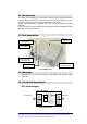
47. Part description
Fig. 35 TFB RF booster
48. Warnings
9
CAUTION! Do not connect the booster to TFA without first switching power
supply off.
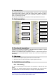
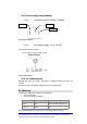
49. Functional description
49.1. Block diagram
Fig. 36 block diagram
AMP
ALC
AMP
High Band Booster
TPA antenna
TFA remote unit
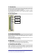
power supply
power on led (green)
alarm led (red)
RF port to TFA
alarm relay contact
(normally closed)
RF port to
coverage antenna
warm side