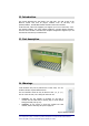
22. Introduction This section describes the TPR family (19” Sub rack). The TPR is part of the Britecell system and host all plug-in modules such as TFL-card, TLC splitter/combiner, TFL-BSI Base Station Interface and control modules. A TPR sub-rack, when fully equipped, can support up to 6 TFL Local Units, one 2way splitter-combiner, two 3-way splitter-combiners, one Base Station Interface, and one control module. Therefore this complete configuration supports up to 24 TFA Remote Units and up to 48 antennas.
5. Functional description The TPR subrack provides: • • • power supply to the active plug-in cards (12VDC); alarm logic and relays; mechanical housing and positioning. 25.1. Block diagram MAINS AC/DC or DC/DC converter backplane, logic & relays DL UL Fig. 24 – TPR block diagram 26. Alarms The TPR sub-rack has a built-in alarm circuit: any fault in TFL or TFA causes a contact relay close or open.
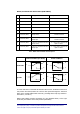
Master/Local Sub-rack Alarm status (SUB-D Male) PIN Name Meaning Description 1 not connected 2 DL Summary Alarm 3 not connected 4 UL Summary Alarm 5 not connected 6 DL Summary Alarm To choose in conjunction with PIN 2, 2 - 6 = Open circuit if Local Sub rack Normally Closed Downlink is in alarm 7 DL Summary Alarm To choose in conjunction with PIN 2, 2 – 7 = Short circuit if Local Sub rack Normally Open Downlink is in alarm 8 UL Summary Alarm To choose in conjunction with PIN 4, 4 - 8 = O
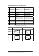
Slave/Remote Sub-rack Alarm status (SUB-D Female) PIN Name Meaning Description 1 UL Summary Alarm To choose in conjunction with PIN 2, 2 – 1 =Short circuit if Remote Sub Normally Open rack Uplink is in alarm 2 UL Summary Alarm Common contact 3 DL Summary Alarm To choose in conjunction with PIN 5, 5 - 3 =Open circuit if Remote Sub Normally Closed rack Downlink is in alarm 4 DL Summary Alarm To choose in conjunction with PIN 5, 5 – 4 =Short circuit if Remote Sub Normally Open rack Downlink is in
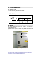
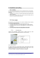
27. Installation and cabling 27.1. Location The TPR sub-rack should be placed as near as possible the BTS or the RF repeater. The sub-rack location should be easy to reach by the users in order to allow alarm monitoring. 9 WARNING! do not close the air circulation subrack grids (top and bottom) with 9 panels or obstacles. If the subrack mounting location does not have a good air circulation, leave at least one unit (1HE) free between subracks. 27.2.
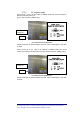
27.2.2. DC negative supply Direct current ( –72 to –36 VDC) apply to TPR922 model only. Power connector is placed on the back panel (see Fig. 27 VDC Connector (TPR922 only)) MALE POWER CONNECTOR FUSE Fig. 27 VDC Connector (TPR922 only) TPR922 model has an internal DC/DC converter: power consumption is the same as above. Direct current (16 to 24 VDC) to be applied to TPR932 model only. Power connector is placed on the back panel (see Fig. 28 VDC Connector (TPR932 only)) MALE POWER CONNECTOR FUSE Fig.
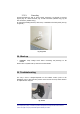
27.2.3. Grounding Ground terminals are part of power supply connectors, as showed in previous figures (Fig. 26 mains connector, Fig. 27 VDC Connector (TPR922 only), Fig. 28 VDC Connector (TPR932 only)). An external grounding terminal, with screw, is available at the back panel (see Fig. 29 ground) Fig. 29 ground 28. Start up WARNING: Verify voltage levels before connecting and powering on the subrack Please refer to system start-up section for further details. 9 29.
TFL-BSI RF attenuator
30. Introduction This section describes the TFL-BSI (Base Station Interface). The TFL-BSI is part of the Britecell system and allows the operator to optimise the signal level the BTS or repeater and the Britecell system. It includes two independent variable attenuators (30 dB, one dB step) for uplink and downlink RF path. A single attenuator version is available, for downlink only or uplink only operations. 31.
33.2. Uplink operation The RF signal coming from the mobile through the TFA and TFL in the uplink direction may not be an optimal level. When this is the case, the uplink attenuator is used to prevent the BTS from being over driven. 34. Installation and cabling 34.1. TPR housing The TFL-BSI is a modular plug-in card designed to be put in a 6 HE sub-rack (TPR family). The TFL-BSI interfaces with the BTS transmitter and receiver through N-female connectors and with Britecell with SMA-female connectors.
TLC RF combiner - splitter
36. Introduction This section describes the TLC splitter/combiner. The TLC is part of Britecell system and provides a family of 2-way and 3-way RF power combiners in order to allow several local interface modules to be connected to common UL and DL RF paths, for interfacing to the BTS. All units have internal pads (one per path) to achieve predefined insertion loss. 37.
THYB common path RF combiner
41. Introduction This section describes the THYB common path RF combiner family. THYB is part of Britecell system and it allows combining of downlink and uplink path into a single one, while maintaining required isolation and stability. This component has been designed for Britecell system configuration requiring single RF connector carrying both DL and UL signals when system is interfaced through a diplexed BTS. 42. Part description DL/UL RF combined input/output Uplink RF input Downlink RF output Fig.
TFB booster
46. Introduction The TFBxx is an optional part of the Britecell system and it’s intended to enhance transmit power of Britecell remote transceivers TFA in order to maintain an output power of 10 dBm per carrier when operating with up to 8 carriers. Typical TFB configuration is together with TFA remote unit and TPA passive antennae. TFB is housed in the same metallic case as TFA and contains one amplifier for each direction (uplink and downlink). 47.
49.2. Description TFB booster is a bi-directional RF amplifier designed to: • improve the coverage area of the antennae connected to the remote unit while maintaining same amount of distributed RF carriers; or • improve number of distributed RF carriers while preserving the same coverage area. Only single band version is available. To enhance both RF ports of TFA remote unit, two TFB boosters are needed. Downlink operation: in downlink path, the booster performs an overall gain of 14 dB.
51.2. Power supply and grounding 51.2.1. Universal mains (85-264VAC, 50/60Hz) Ground Mains Mains Fig. 38 -Mains connector 51.2.2. DC negative supply –72 to –36 VDC. DC connector and part number: Fig. 39 - VDC connector 51.3. RF combined ports Antenna port must be directly connected to radiating antennas through RF jumpers. TFA port must be connected to combined port of TFA remote unit. 52.
53. Troubleshooting In case of alarm LED is active, check first if the air circulation around the unit is acceptable and that environmental conditions (operating temperature, supply range) are among specified operating limits. If problems persists please refer to service or technical support.
TPA antenna
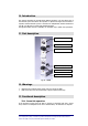
54. Introduction This section describes the TPA antenna family. The TPA is part of Britecell system and provides the field shaped coverage. TPA realises the physical radiating points, for radio transmission/reception, towards mobile stations. Each TPA is connected to the relevant Remote Unit TFA by means of coaxial jumper. TPA family ranges from single band stand-alone to dual band Fig. 40 TPAx10 single band antenna Fig. 41 TPAx20 dual band antenna Fig.
55. Functional description The TPA extends cellular coverage in such indoor environments that can't be economically and easily reached by radio mobile network signals. RF signals going through walls, metallic structures and any other obstacle inside buildings are attenuated up to 1000 times (30 dB), thus creating problems for the users of mobile phones.
56. Installation and cabling 56.1. Location Britecell transmits low-power radio signals in a given area. It is important to respect the simple installation instructions as follows, in order to achieve a good communication quality and to avoid malfunctions, which could bring to a selfinhibition of the device. The TPA passive antenna’s placing should be chosen in order to grant the maximum indoor radio coverage. The largest field is located perpendicular to the TPA.
56.2. Location examples Fig. 46 Rectangular room Fig. 47 Corridor Fig. 48 Garage 56.3. Wall mount Fig. 49 Front view fig. 50 Side view BRITECELL System Manual MN010-04 June 2003 Page 59 of 78 The company has a policy of continuous product development and improvement and we therefore reserve the right to vary any information quoted without prior notice.
56.4. Connectivity There is either an N-female connector or a RG223 pigtail attached to the TPA antenna to realise connection to the TFA. 9 WARNING: use only low loss 50Ω RF cable to connect TPA antenna to TFA. 9 WARNING: do not connect the antenna without switching off the power supply to the TFA. 57. Troubleshooting & maintenance The device has no particular maintenance requirements.
SYSTEM INSTALLATION
58. Installation and cabling Britecell is designed to be simple and fast to install and commission. It requires a minimum number of tools and equipment. However, it is necessary to observe local regulations when planning and implementing an RF system and safety conventions must be strictly adhered to at all times.
For in-building applications the most common fibre cables are tight buffered cables with 2 fibres; examples are: Duplex zip-cord: two simplex units in a zip cord configuration. External Dimension (mm) 2.5 x 5.3 Maximum Tension (kg) 30 Weight (kg/km) Minimum Bend Radius (mm) 11 30 (minor axis) Duplex breakout cable: two individually coloured simplex units over sheathed in a “figure 0” configuration. External Dimension (mm) 3.
58.3.2. Optical Cable Laying Fiberoptic cables can be pre-terminated with appropriate fibre connectors, however, this often times causes problems if there is not enough space to pull through the connector, or if the cable lengths become very large. A qualified installer can make a recommendation on this matter. It is always recommended that extra fibre length be provisioned.
58.4. Power Supply A Britecell system may be locally (at each remote unit) or distributed powered. There are advantages with both methods. It may be faster and cheaper to use local power, however it is easier to back-up a system when the power originates at a single point. A power supply may be distributed in a composite cable (copper and fiber), or two separately parallel cables may be run.
60. MAINTENANCE 60.1. Plug-in cards removal 9 Always switch off subracks power supply before removing or inserting any active plug-in card. 60.2. Optical equipment It is a good rule when working with the fibre optic components, to always have available the appropriate screw covers for closure of the optic connectors that are not connected. The intrinsic fragility of an optic connection must be highlighted. A minimum layer of dust causes a notable increase of the insertion loss, therefore.
OTHER INFORMATION
61.
In case the product is out of warranty, the customer will be informed about the cost for repairing or replacing the unit. The service will be provided only after receiving Customer’s authorisation. Before returning the goods, the customer should give prior notice to Allen Telecom through normal return authorisation procedure. Allen Telecom aims to offer an excellent service.
63. DECLARATION OF CONFORMITY Allen Telecom Declares That the device related to this usage and maintenance handbook comply with the CE mark requirements, according to the Low Tension Rules 73/23/CEE and Electro-magnetic compatibility Rules 89/392/CEE Allen Telecom will carefully retain the technical file related to the device design, together with this usage and maintenance handbook, for a minimum time span of 10 years. Signature: Managing Director of Tekmar Sistemi S.r.l. 64.
APPENDIX
65. APPENDIX A - Britecell system design basics 65.1. Indoor propagation Radio signals from wireless mobile telephone systems are located in the high UHF spectrum, between 800MHz and 2,2GHz, according to the common standards such as ETACS, AMPS, GSM, DCS, PCS, UMTS, etc.. At such high frequencies electromagnetic waves are subjected to phenomena like diffraction and reflection; these effects become dominant in cellular systems where propagation rarely occurs in free space.
65.2. Fibre-optic transmission Britecell uses an analogue modulation scheme for the transmission of the composite RF signal through the fibre optic link; the optical carrier is intensity modulated. Distortion is critical in cellular systems due to the multiple carriers present and the regular channel spacing ensures that the products usually occur on the frequency of another channel.
65.3. Coverage method The greatest benefit of Britecell fibre optic distribution system is the possibility to place non obtrusive antennas where the coverage is needed, i.e. near the mobile users. The coverage targets, in terms of signal levels, are meant to be achieved by placing radiating points inside the building. Antenna locations are selected in order to: • minimise path loss to mobiles in the public areas of the building, • minimise number of remote antenna sites.
66. APPENDIX B - Britecell input power level setting 66.1. Down link power levels In order to achieve spurious products below the limits set forth in various governmental specifications (eg. -36 dBm for GSM900, –30 dBm for GSM1800) the input power at the TFL downlink input port should be set according to the following table. FCC specifications (-13 dBm- AMPS, PCS) are somewhat more lenient and are also dependent on spectral mask requirements.
66.2.
67. APPENDIX C - Classifying hazardous areas Hazardous Area A hazardous area is defined as: "An area in which a flammable substance in the form of gas or vapour or dust, when mixed with air, is present in such proportions that it can explode when in contact with an ignition source.
68.