
User's Manual

WLS Installation and Maintenance Manual Installation
Geometrix
®
Wireless Location System 23
Andrew Corporation Proprietary
2.10 Diagnostics & Verification
A software utility is run on the WLS to verify the installation. It is assumed the installer/tester has
a general knowledge of basic PC operation.
The software will perform a comprehensive check of WLS hardware, WAN connectivity, and
external cabling. Results will be presented in a simple pass/fail manner not requiring the user to
interpret any data. A series of tests will be initiated each displaying a PASS/FAIL indicator and
then a summary PASS/FAIL result will be displayed.
The diagnostic software will not impact the WLS in a negative manner when executed
immediately following initial WLS power-up.
2.10.1 Initial Set-up
1. Place the base station power panel circuit breaker in the ON position
2. Place the WLS rear-panel switch in the ON position. Verify that the WLS front panel ON
LED is illuminated and the WLS cooling fans are running.
3. Wait approximately 5 minutes for the WLS to connect to the GCS and for synchronization
to the latest software configuration. If a new WLS configuration is required, the WLS will
re-boot (lights flash) during software update. If successful, the front panel ONLINE light
will illuminate. If not, further diagnostics are required. In either case, run the system
diagnostics program as shown in the following steps.
4. Connect the laptop serial port to the WLS front panel DB-9 RS-232 port via a serial null-
modem cable.
5. In HyperTerminal, or similar utility, connect to the WLS using serial port settings of
57600-8-N-1 with no flow control.
Note: NMS access to WLS diagnostics is provided and replaces the individual telnet sessions.
Diagnostics is started from the NMS. The results are reported back to the GCS and stored in a
database. The results of the diagnostics test utility may also be run remotely, via a telnet
connection into the WLS. To accomplish this, steps 4 and 5 may be replaced by executing telnet
<IP address> from a GCS command prompt. The WLS <IP address> may be obtained from the
GCS Network Management System WLS site detail screen.
6. Login as root.
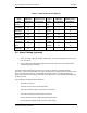
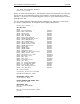
7. Type diagnostics to run the WLS diagnostics program. The following menu will appear:
DIAGNOSTICS Main Menu [v5.4.0]
0) Exit
1) Tests (2-6)
2) Back plane
3) BPU/RX
4) Noise Correlation/Power
5) Mezzanine
6) GPS
7) AOA Calibration
8) Rf Cabling
9) WAN Port/Ping
10) COM Port
11) Alarm Contacts