
User's Manual

WLS Installation and Maintenance Manual Installation
Geometrix
®
Wireless Location System 22
Andrew Corporation Proprietary
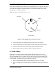
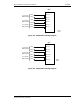
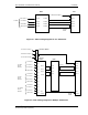
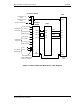
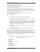
Figure 2-10 Dual-band Combiner TDOA Cabling Diagram
2.9 GSM BCCH Antenna Cabling (GSM only)
In GSM base station installations the WLS requires a forward channel RF signal connection for
BCCH synchronization. The WLS GSM port may be connected to an interior whip antenna, an
exterior whip antenna, or a BTS monitor port (existing or via an installed directional coupler).
Signal levels at the WLS shall be maintained between -40dBm and -90dBm. One cable shall be
provided to the WLS. If separate BCCH monitor ports are used for each sector, the sector
signals shall be summed together (e.g. using a 3x1 splitter) to a single RF cable for input to the
WLS.
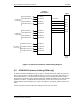
Connect the BCCH antenna cable to the GSM port on the rear of the WLS.
ANT 1
WLS
ANT 2
ANT 3
ANT 9
A2 SUM OUT
C1 SUM OUT
B1 SUM OUT
A1 SUM OUT
Antenna
RF Combiner
To A Sector
Antennae
A1 800 IN
A1 1900 IN
ANT 10
ANT 11
C2 SUM OUT
B2 SUM OUT
A2 800 IN
A2 1900 IN
800 MHz Alpha 0
1900 MHz Alpha 0
800 MHz Alpha 1
1900 MHz Alpha 1
To B Sector
Antennae
B1 800 IN
B1 1900 IN
B2 800 IN
B2 1900 IN
800 MHz Beta 0
1900 MHZ Beta 0
800 MHz Beta 1
1900 MHz Beta 1
To C Sector
Antennae
C1 800 IN
C1 1900 IN
C2 800 IN
C2 1900 IN
800MHz Gamma 0
1900 MHz Gamma 0
800 MHz Gamma 1
1900 MHz Gamma 1
WLS4
shown