
User's Manual

WLS Installation and Maintenance Manual Installation
Geometrix
®
Wireless Location System 15
Andrew Corporation Proprietary
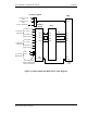
Power cables are shipped with the circular connector already installed. The opposite cable end is
cut to length and terminated with ring terminal lugs during installation. Part number G15A0497-1
is the power cable supplied for 24 VDC installations. Part number G15A0497-2 is the power
cable supplied for –48 VDC installations.
NOTE: The RFDU is only available for 24 VDC use.
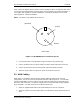
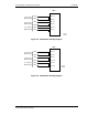
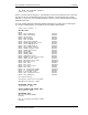
Figure 2-4 WLS/RFDU Power Connector Pin-out
1. Cut the power cable to the appropriate length and crimp on ring terminal lugs.
2. Connect the black lead of the power cable to the base station power panel return bus.
3. Connect the red lead to the base station power panel WLS breaker terminal.
4. Attach the power cable to the WLS rear panel circular power connector.
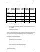
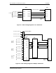
2.5 WAN Cabling
WAN cables are available in different lengths with both DB-25 and Winchester connector
configurations. Do not exceed the V.35 standard maximum cable length of 50’. For CSU/DSU
V.35 port compatibility reference, Table 2-1 lists the cable pin assignments for both DB-25 and
Winchester style connectors. The WLS is configured as a DTE interface with clocking supplied
by the CSU/DSU. The WAN connector on the WLS is DB-25 male.
1. Attach the supplied WAN cable to the DB-25 WAN port on the rear of the WLS.
2. Attach the opposite end of the WAN cable to the CSU/DSU V.35 port provisioned for the
WLS.
(+24V)
Return
Front View
(Unused)