
User's Manual

Geometrix
®
Wireless Location System 11
Andrew Corporation Proprietary
Chapter 2 Installation
This chapter details the step-by-step procedures for installation of a new WLS unit. Procedures
should be followed in the order presented.
2.1 Pre-Planning
Prior to beginning an installation, the following base station items should be in place:
• 19” or 23” Rack Space – 3.5” of vertical space for the 2-channel WLS, 5.25” for the 4-
channel WLS, 5.25” for the RFDU. An additional 1.75 “ is required for the Antenna
Switch if applicable, and an additional 1.75” is required for the dual-band combiner if
applicable.
• Power – One dedicated minimum 10A breaker tagged for the WLS equipment, 5A for
RFDU, and 20A for Andrew Corporation outdoor enclosure.
• CSU/DSU Port – One V.35 port provisioned and actively cross-connected to the GCS.
One 56k/64k DS0 connection, nailed through from the WLS to the GCS is required.
• Multi-coupler ports (TDOA only) – One active port on each receive antenna multi-
coupler.
• AOA antenna(s) (AOA ONLY) – Antenna panel(s) mounted on the tower/building and
cabled into the base station shelter RFDU.
• GPS Antenna – New antenna installed or existing antenna accessible for GPS splitter
installation.
• Chassis Grounding – One ground connection location in the WLS equipment rack.
• Alarm Termination (if applicable) – One set of terminals on alarm panel tagged for WLS
equipment.
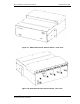
The WLS equipment is typically shipped in two NEBS GR-63 qualified packages. One contains
the WLS unit and the second contains the site-specific installation kit. The installation kit contains
all cabling, mounting hardware, grounding supplies and GPS supplies required for installation.
The following tools and supplies are the minimum required for installation:
• #2 Phillips Head Screwdriver
• 3/16” Blade Flat Screwdriver
• T10 Torx Screwdriver
• T20 Torx Screwdriver (or #2 Phillips Screwdriver depending on HW provided)
• Diagonal Flush Cutter