
User's Manual
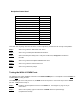
Table Of Contents

Step 3.
Remove the loopback connector.
Step 4.
Install the 9 pin loopback connector for the COMM test. See Diagram 5, page 47 for
pin connections.
Step 5.
When at the # prompt, type the command: testCOM. Watch for pass/fail reply.
(Loopback Succeeded)
Step 6
. Remove the loopback connector.
If the data reads anything other than the above, contact engineering to determine the severity of the problem.
Testing The BPU Board
Step 1
. Change directory with the command: cd /ram/bpu/qnx/bin.
Step 2.
When at the # prompt, type the command: btest-b0. This will test bpu0. All tests
should say passed or skipped. The end of the test should read btest ok.
Step 3.
When at the # prompt, type the command: btest-b1. This will test bpu1. All tests
should say passed or skipped. The end of the test should read btest ok.
NOTE: The bpu.ini file in the /ram/bpu/qnx/config directory needs to be activated for the 2
nd
bpu tray
before it will show up as OK in the status word function of the testCtrl test.
If the data reads anything other than the above, contact engineering to determine the severity of the problem.
Testing The Mezzanine Board (For CDMA Only)
Step 1.
Change directory with the command: cd /ram/bpu/tester.
Step 2.
Type the command: /unzip_mcs_files &.
Step 3.
When at the # prompt, type the command: mztest. Watch for pass/fail reply.
Step 4.
Select 4 to perform Sim Data tests.
Step 5
. Select 3 to run both tests. Confirm test passed.
Step 6
. Select 0 to exit sim data test menu.
Step 7.
Select 0 to exit mztest test menu.
If the data reads anything other than the above, contact engineering to determine the severity of the problem.