
User's Manual

WLS Installation and Maintenance Manual Equipment Description
Geometrix
®
Wireless Location System 8
Andrew Corporation Proprietary
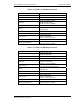
Table 1-5 PCS RFDU Specifications
Frequency Range 1850 - 1910 MHz
Gain 14 –20 dB
Passband Return Loss 15.0 dB min
Impedance 50 ohms
Rejection
60 dB min. ( DC - 1825 MHz )
60 dB min. (1930 - 4000 MHz )
40 dB min ( 4000 - 6000 MHz )
Noise Figure 2.0 dB max
OIP3 +35 dBm min.
Temperature Range
-30°C - +70°C
Dimensions 19" and 23" Rack Mounting
Connectors
Input: TNC female
Output: TNC female
Power – Three pin circular
Max input level: +10 dBm
Power Requirements 26.5 Vdc @ < 0.8A
Operates over 19 – 36Vdc
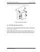
1.4 Dual-band RF Combiner
For co-located dual-band installations (e.g. PCS overlay), an external RF combiner module is
available. This unit passively combines inputs from 2-antenna systems into one WLS input,
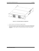
which processes signals from both bands. Figure 1-9 illustrates the connections to the Dual-
Band Combiner.
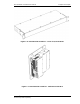
Figure 1-9 Dual-Band RF Combiner – Rear View
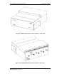
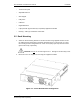
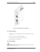
The dual-band combiner may be installed as a 1U rack-mount unit as shown in Figure 1-10, or
may be “piggy backed” on the WLS for wall mount installations using available brackets as shown
in Figure 1-11.