
User's Manual

WLS Installation and Maintenance Manual Equipment Description
Geometrix
®
Wireless Location System 2
Andrew Corporation Proprietary
GSM
BCCH
Antenna
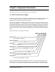
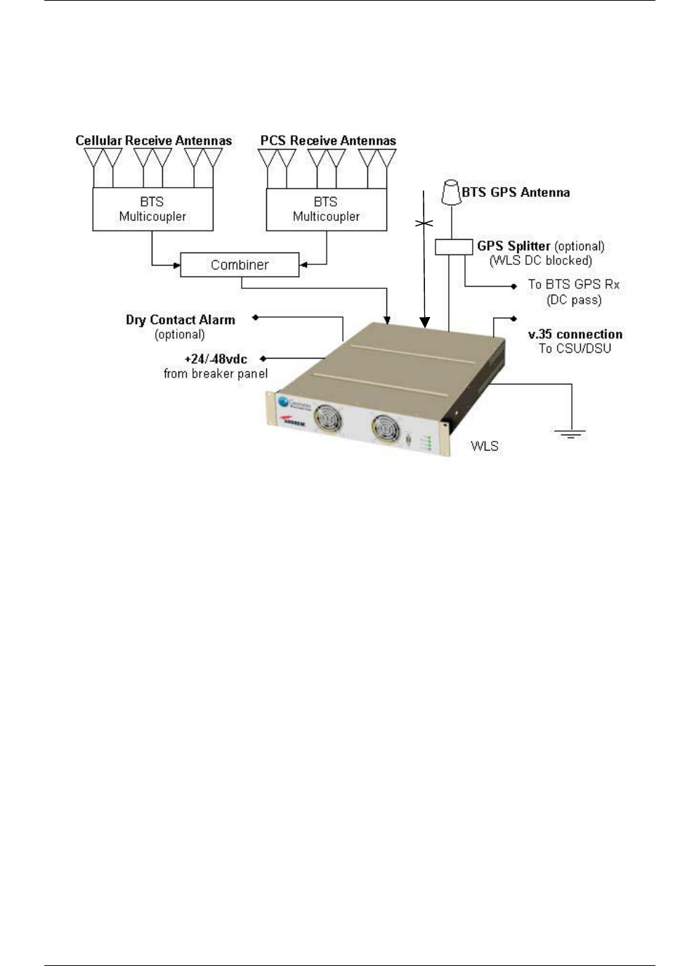
the installation of separate antennas and associated RF conditioning hardware. Figure 1-1
illustrates the WLS base station connections.
Figure 1-1 WLS Base Station Connections
For modular-cell, micro-cell, or outdoor shelter installations, a self-contained environmentally
protected enclosure is available. The outdoor enclosure is designed for flexible mounting options
including on top of an existing enclosure, the side of a shelter, or to an existing pole.
For co-located dual-band installations (e.g. PCS overlay), an external RF combiner module is
available. This 1U rack-mount unit passively combines inputs from 2-antenna systems into one
WLS input. One WLS is used to process signals from both bands.
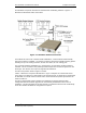
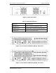
The WLS front panel is shown in Figure 1-2 below.
Table 1-1 defines the front panel LED indicators. Figure 1-3 depicts the 2-channel WLS rear
panel, Figure 1-4 shows the 4-channel WLS rear panel and Figure 1-5 shows the 4-channel WLS
for AOA with an external antenna selector switch. Environmental and power specifications are
shown in Table 1-2.
The WLS is shipped with system software pre-installed on the internal solid-state disk.
Configuration data and software upgrades are automatically downloaded from the GCS at
installation. The WLS maintains up-to-date software in coordination with the GCS automatically.
No on-site software installation or configuration is required.