
User Manual


GWMT Transmitter Manual Chapter 6: Brief Technical Description 17
Chapter 6: Brief Technical Description
Introduction
This chapter includes information on how the transmitter hardware functions. This information is
presented so that the user may have a better understanding of how the unit works.
Note: There are no field repairable assemblies in the transmitter.
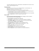
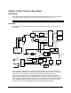
Overview
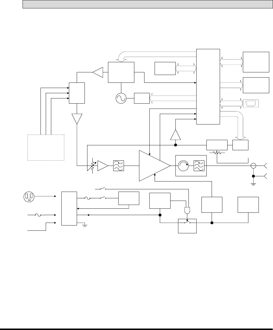
The GWMT is a self-contained transmitter for the specified frequency band. A block diagram is
shown below.
DC-DC
Converter
VCTCXO
14.4 MHz
Synthesizer Module
PA
Detector /
Controller
D/A
Converter
PA ENABLE
PA TEMPERATURE
ALC
AC Power
Supply
Power
Connector
Controller
ALC
EEPROM
(Cal Data)
5 x 4 Keypad
LCD
RS-232
AC Power
Cord
DC Power
Cord
+24 V
Fans
I/Q
Modulator
I
REFERENCE
Q
Modulation
Mezzanine
Board
(future option)
Window
Comparator
10 - 18 V
FET
Switch
+
-
Power
Switches
+12 V
Isolator / LPF
LOCK DETECT
RF
Output
D/A
Converter
The RF signal is generated in the synthesizer module, which derives its reference from an on
board TCXO. The synthesizer tunes in steps appropriate for the frequency band. Following the
synthesizer is an I/Q modulator, included for future applications requiring modulation.
The modulator output is applied to a variable attenuator, and then to the power amplifier. A
sample of the PA output is coupled to a level detector / controller IC, which also receives a set
point voltage from a digital to analog converter. This IC develops an error voltage that is applied
to the variable attenuator, forming an automatic level control loop. The level set point value is
derived from values stored in EEPROM, which are determined at unit calibration.