
User Manual


GWMT Transmitter Manual Chapter 4: Installation and Operation 9
Chapter 4: Installation and Operation
This chapter covers the installation, set up and operational features of the GWMT transmitter.
Installation Procedure
Remove the transmitter from the shipping container and install it in a location with an ambient
temperature range between -20 and 55°C.
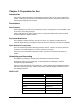
Operation
Power Source
Connect either the AC power cord to a source of 110/220 Vac 50/60 Hz or the DC power cable to
11-15 Vdc capable of 20 A. The AC input is fused on the front panel and the DC power cable
contains an inline 30A fuse and reverse polarity protection. The front panel Power switch controls
the primary power that is connected to the side panel.
Battery Operation
Connect the DC cable to the GWMT and either a 12 volt battery or a 12 volt power supply
capable of 20 amps. An internal voltage monitoring circuit will disable the transmitter when the
internal voltage drops to approximately 11 volts. The front panel will then display “LOW BATT.”
To restore operation, recharge or replace the battery and then resume testing.
Note: Long cables or poor connections will create a voltage drop that will cause the
transmitter to shut down prematurely.
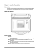
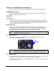
Antenna Connection
Connect the RF cable from the RF Connector (Type N Female) located on the side of the
transmitter to an appropriate antenna.
Note: For GWMT 2120 transmitters only, an external bandpass filter is required if the
transmitter is collocated near RF sensitive equipment. The use of this filter and
associated cables results in a loss of approximately 1 dBm in output power.
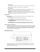
Frequency Control
The desired frequency can be entered either directly using the numeric keys, or it can be scrolled
to by using the up and down arrow keys. The keypad sequence is as follows:
Push the Frequency (FREQ) button. Notice that the flashing cursor moves to the left-most digit of
the frequency value.