
User Manual


8 Chapter 3: Interface Description GWMT Transmitter Manual
Numeric Keys
0-9, decimal pt: The numeric keys are used to directly enter frequency or amplitude values.
CLR: The CLR key reloads the last valid frequency or amplitude entry.
Function Keys
↑,↓: The Arrow keys are used for scrolling to select frequency or amplitude values, and to
adjust the visibility of the LCD display in conjunction with the Enter key.
BACKLIGHT: The Backlight key toggles the LCD display backlight between on and off.
ENTER: The Enter Key is used to activate frequency and amplitude entries and to adjust the
visibility of the LCD display in conjunction with the Arrow keys.
Display LCD
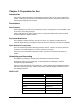
The Display LCD consists of 4 lines of 20 characters. Each line serves a different function, as
described below:
Line 1: Frequency: indicates the transmit frequency in MHz.
Line 2: Amplitude: Indicates output power in 0.1dB increments
Line 3: Modulation: Indicates on/off state of Modulation (not implemented) and the
Transmitter (RF On/Off)
Line 4: Diagnostic: Displays internal DC voltage and operating temperature of the
transmitter in degrees C. Error messages are also displayed on this line when required.
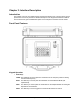
Power Switches and AC Fuse
An AC power switch and a DC power switch are located on the upper right side of the front panel.
When using an AC power source, both power switches must be in the “on” position for transmitter
operation. When using a DC power source, the DC power switch must be in the “on” position for
transmitter operation (the AC power switch can be in either position). The AC fuse holder is
located directly above the DC power switch.
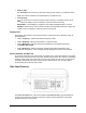
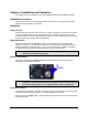
Side Panel Features
The Power Connector (AC or DC Power Cable) and the RF Connector (Type N Female) are
located on the side panel. The DB-9 connector is used by Grayson Wireless for internal test
purposes and has no user function.