GWMT TRANSMITTER USER’S MANUAL Manual Part No. MN002402 Rev. B Issued 12/2001 Manual Assembly Instructions Print this manual (double sided pages) on 20 lb.
GWMT TRANSMITTER USER’S MANUAL Manual Part No. MN002402 Rev.
COPYRIGHT Copyright © 2001 Allen Telecom Inc. All rights reserved. All rights reserved. This document, and the Allen Telecom software to which it refers, are protected by copyright. Both this document and the Allen Telecom software are furnished under license as provided in such software and may be used only in accordance with that license.
TABLE OF CONTENTS PREFACE__________________________________________________ v Certification ____________________________________________________________________ v Warranty ______________________________________________________________________ v In Case of Trouble _______________________________________________________________ v Chapter 1: Introduction ______________________________________ 1 About This Manual___________________________________________________________________ Contacting Grayson Wireless ___
Chapter 5: Performance Specifications ________________________ 13 General __________________________________________________________________________ Outside Dimensions and Weight ___________________________________________________ Input Power ___________________________________________________________________ Device Control LCD Display and Keyboard ___________________________________________ RF Connection _________________________________________________________________ Temperature Range ___________________
PREFACE Certification Grayson Wireless (hereinafter called “GW”) certifies that this product met its published specification at time of shipment from the factory. Warranty GW warrants to the original purchaser (hereinafter called “Buyer”) that Equipment manufactured by GW shall be free, under normal use and service, from defects in material and workmanship for a period of twelve (12) months from the date of delivery to the Buyer (the Warranty Period), and shall conform to GW’s specifications.
Chapter 1: Introduction About This Manual This manual provides an overview of the GWMT Transmitter family. These transmitters are the propagation test configuration partners for the Invex3G data collection platform receivers. Also included in this manual are procedures for unpacking, inspecting, and setting up the product for operation. Contacting Grayson Wireless Grayson Wireless is a worldwide leader in test and measurement products for the wireless industry.
Sales The Grayson Wireless team of sales engineers can be reached Monday through Friday from 8:00 AM to 5:00 PM Eastern Standard Time. Please contact your sales representative for information about the complete line of Grayson Wireless measurement products. United States Telephone: (434) 386 – 5300 Fax: (434) 386 – 5324 Toll-free: (800) 800 – 7465 World Wide Web: www.grayson.com E-mail: sales@grayson.
RF Exposure IMPORTANT NOTE: To comply with FCC RF exposure compliance requirements, the following antenna installation and device operating configurations must be satisfied: During normal use the antenna must be fixed-mounted on outdoor permanent structures with a separation distance of at least 6 meters from all persons and must not be co-located or operating in conjunction with any other antenna or transmitter. The maximum allowed antenna gain is xx dBi.
Chapter 2: Preparation for Use Introduction This chapter outlines precautions and preparations necessary prior to use of the measurement system. Unpacking and inspection of the individual pieces, plus the requirements placed on the external power supply are also covered. Precautions Shock Hazard When replacing the AC fuse on the front panel, be sure to unplug the line cord and replace it with a fuse of the correct rating and type.
Chapter 3: Interface Description Introduction This chapter covers the front panel features and external interface ports. The first section gives a pictorial view of the front panel and a detailed description of the keypad and resultant indicators. The second section gives a detailed description of the side panel connectors and fuse holder. Front Panel Features Keypad Operation Mode Keys FREQ: The FREQ key is used to place the transmitter into the Frequency Mode for setting the transmitter frequency.
Numeric Keys 0-9, decimal pt: The numeric keys are used to directly enter frequency or amplitude values. CLR: The CLR key reloads the last valid frequency or amplitude entry. Function Keys ↑,↓: The Arrow keys are used for scrolling to select frequency or amplitude values, and to adjust the visibility of the LCD display in conjunction with the Enter key. BACKLIGHT: The Backlight key toggles the LCD display backlight between on and off.
Chapter 4: Installation and Operation This chapter covers the installation, set up and operational features of the GWMT transmitter. Installation Procedure Remove the transmitter from the shipping container and install it in a location with an ambient temperature range between -20 and 55°C. Operation Power Source Connect either the AC power cord to a source of 110/220 Vac 50/60 Hz or the DC power cable to 11-15 Vdc capable of 20 A.
If entering the value directly, enter the value using the numeric keys, including the decimal point and fraction (KHz), followed by the Enter key. The display will automatically adjust your entry to the nearest valid frequency setting that is less than or equal to the value entered. If scrolling, press the up or down arrow keys repeatedly until the desired value is obtained. The display will automatically increment (decrement) to the next (previous) valid frequency each time one of the keys is pressed.
continuously updated with the status of the transmitter; if the transmitter turns off due to an error condition, this will be displayed on line 4. Display Control There are two types of control for the LCD: Backlight ON/OFF, and Contrast Adjust. The Backlight key toggles the LCD backlight on and off.
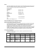
Chapter 5: Performance Specifications General Outside Dimensions and Weight Height 6.54 inches Width 16.1 inches Depth 14.5 inches Weight < 30 lbs Input Power 110/220 VAC 50-60 Hz (<300 W) or 11-15 VDC (20 A) Device Control LCD Display and Keyboard Frequency Select Output Power Select, 0.
Output Power Flatness over Temperature and Frequency +1 dB (20 to 43 dBm Output, 0o to +40o C) Output Impedance 50 ohms Output VSWR < 1.
GWMT 1920 Frequency Range 1850 - 1990 MHz Frequency Tuning Step Minimum 30 / 50 kHz GWMT 2120 Frequency Range 2110 - 2170 MHz Frequency Tuning Step Minimum 50 kHz GWMT Transmitter Manual Chapter 5: Performance Specifications 15
Chapter 6: Brief Technical Description Introduction This chapter includes information on how the transmitter hardware functions. This information is presented so that the user may have a better understanding of how the unit works. Note: There are no field repairable assemblies in the transmitter. Overview The GWMT is a self-contained transmitter for the specified frequency band. A block diagram is shown below.
The power amplifier is protected from high VSWR loads by an isolator at its output. The PA also provides a temperature sense signal to the controller, which disables transmission if temperature is excessive. The transmitter is designed to operate from a nominal 12 VDC source. A DC-DC converter is included to convert the 12 V input to 24 V required for the PA. Circuitry senses the input DC voltage, and disables the transmitter if an under voltage or over voltage condition is detected.