
User's Manual

Andrew Corporation
Proprietary – Use pursuant to Company Instruction
7 of 8
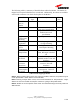
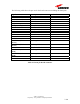
The following table shows the pin out for the D-sub connector including the alarm pins.
Signal Description Pin Number
Manual Control Control ON/OFF 1
GND Ground 2
PA-Enable-Actif + Control 3
PA-Enable-Actif - Control 4
PA_Presence_Reset Towards Micro Controller 5
GND_Presence_Reset Ground 6
Reserved Not allowed for the MCPA 7
GND Ground 8
Reserved Not allowed for the MCPA 9
Reserved Not allowed for the MCPA 10
GND Ground 11
Reserved Not allowed for the MCPA 12
Red LED LED 13
UART TX + (TRM to
MCPA)
Exchanged Information 14
UART TX - (TRM to
MCPA)
Exchanged Information 15
Reserved Not allowed for the MCPA 16
UART RX + (MCPA to
TRM)
Exchanged Information 17
UART RX - (MCPA to
TRM)
Exchanged Information 18
GND Ground 19-24
Green LED LED 25
Table 3: Pin out for D-Sub connector