
User's Manual

RF Power Amplifiers
Andrew Corporation – Power Amplifier Group
Propriety – Use pursuant to Company Instruction
3 of 3
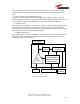
This stage brings the signal to its desired high power level, it is the heart of the RF
section of the unit. The unit power, linearity and efficiency directly come from this
block.
− Power conversion and conditioning circuit
This block is made of a DC/DC converter and various voltage regulators to do the
interface between the customer supply network and the internal functions of the unit. It
provides all the voltages and signal interface to the internal blocks of the unit.
− Controller circuit
This block is the “intelligence” of the unit, it is based on the CPU and computes all the
internal functions of the unit. These are the power up sequences, the performances
compensation over temperature, manages the monitoring and control of the unit, it also
records many events in the so called flight recorder .
− Communications circuit
The communication circuit is associated to the controller circuit to communicate with
the outside world. It handles the customer specific protocol to bring in and out all
monitoring and control commands.
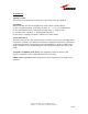
Figure PA Configuration
Analogical
interface
Power Supply
distribution. Current
measurement
-48V power supply Analog
interface
RF
PART
RF input
Power
detector
RF Output