
User's Manual

RF Power Amplifiers
Andrew Corporation – Power Amplifier Group
Propriety – Use pursuant to Company Instruction
4 of 6
Control System:
The MCPA will work with the customer BTS which control and monitor the MCPA by
the specified interface protocol.
A microprocessor controller is inside the MCPA to be compatible with the customer
interface protocol and assures the MCPA performance meet the specification. The micro-
processor controller is used to enable the PA to start/stop working, control the amplifier
alarm system, control environmental compensation of the amplifier, and to maintain a
linearization solution for the pre-distortion circuit.
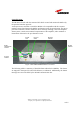
Figure 1 45W UMTS 850MHz MCPA Front Panel
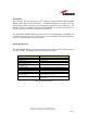
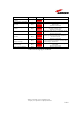
The following table is a summary of detailed alarms within the PA Module. The alarms
are mapped to front panel bi-color LED behavior, as indicated. Additionally, the alarms
messages are sent to the BTS by the RS-485 communication bus.
Bi-color
LED
DC power
Switch
RS-485
communication
connector
DC power
connector
RF output
connector
RF input
connector