
Instruction Manual
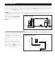

DRAIN INSTALLATION
The drain outlet on the dehumidifier can be hard piped using a 3/4" PVC Slip x 3/4" MNPT fitting and 3/4" nominal drain tubing or the provided 3/4"
MNPT x 3/4" hose barb fitting and 3/4" clear PVC tubing can be used to drain the dehumidifier. Always maintain a constant downward slope from the
dehumidifier to the drain and do not allow soft tubing to curl up which may result in air lock. NOTE: PTFE thread seal tape is recommended for the
threaded connection and hand tighten only. If hard pipe is used, PVC primer and cement is recommended for the slip fit connection.
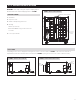
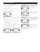
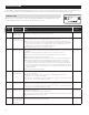
LEVELING
The feet can be adjusted to level the unit, and if
required, to accommodate drain fittings and a
secondary condensate pan. Leveling is required to
ensure proper drainage from the dehumidifier. See
FIGURE 5.
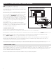
CONDENSATE PAN, CONDENSATE PUMP AND FLOAT SWITCH
A condensate pan is recommended when suspending
the dehumidifier over the canopy. Adhere to local
codes regarding draining of the condensate pan. If a
condensate pump is needed, install it in the condensate
pan as well.
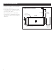
Install a condensate overflow safety switch (i.e. float
switch) in the condensate pan, remove the factory
installed jumper wire between the Float Switch
terminals on the control and wire the float switch to the
dehumidifier as shown in FIGURE 6. Overflow safety
switches on condensate pumps can be wired to the
Float Switch terminals in a similar fashion.
0.38" MIN
2.00" MAX
3/4" FNPT DRAIN
FLOAT
Switch
DH DH
NORMALLY CLOSED
FLOAT SWITCH
90-2305
90-1857
FIGURE 5 – LEVEL THE UNIT
FIGURE 6 – FLOAT SWITCH WIRING
5