— 21 —
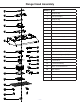
Assembly
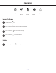
Circuit Diagram
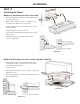
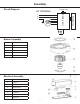
Blower Assembly
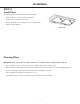
Electrical Assembly
Number Part
1 Screws
2 Box
3 Transformer
4 Terminal
5 Box base
6 Connector
7 Capacitor
Number Part
1 Ring
2 Blower
3 Propeller
4 Motor
5 Bracket of Motor
L
N
E
M
Push Button
Capac itor
binding post
AC 120V 60Hz