20 Meter 220x100x4 3M Uprights ASSEMBLY INSTRUCTIONS 800-544-4445 • 812-867-2421 www.anchorinc.
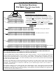
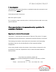
X-CABLING PATTERNS For Anchor Structures 20m Span (220 x 100 x 4mm Profile) 2-28-05 PRIMARY ROOF CABLES “X” SIDE VIEWS SHOWN SECONDARY ROOF CABLES “V” ENGINEERING RULES FOR PROPER X-CABLING 1. All 20m Structures require primary roof and side x-cabled end bays. 2. Structures with 6 or more total bays also require secondary x-cables in the roof section only of the second bays. Viewed from above, these form a “V” shape. (Structures with 5 bays or less do not require secondary cables in the second bay.
BT 2000 240/300 570/627 Copyright: Without our written consent the disclosure, reprinting, copying and reproduction of this publication, whether in full or in part, are prohibited. 2 Spanning the world.
BT 2000 240/300 570/627 Index 1 Introduction..............................................................................4 1.1 General notes ...................................................................................... 5 1.2 Construction tools ............................................................................... 7 2 Staightening of the tent any laying of the baseplates.................8 2.1 Laying of the baseplates ......................................................................
BT 2000 240/300 570/627 1 Introduction The following instructions describe in a methodical plan the construction and erection of your RÖDER tent. Follow always these instructions. Work from point to point. If it is necessary, there are extra points, in which you have to take care or pay special attention. Please pay attention to the appropriate safety regulations for prevention of accidents. Regarding the contents of this document: The points 1-5 describe the construction of the tent.
BT 2000 240/300 570/627 1.1 General notes Before starting construction you must read this documentation exactly. If the points are clear and the building components are identified and ready, then start construction and follow the instructions step by step. Pay attention to the safety regulations for prevention of accidents. The life of the helpers may be in danger due to the lack of knowledge and poor observation of the given regulations. Work on every point of the instructions chronologically.
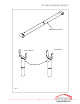
BT 2000 240/300 570/627 Measuring rod 5m Fork 80mm Fork 140mm Mounting rods Pic. 1 6 Spanning the world.
BT 2000 240/300 570/627 1.2 Construction tools The construction and dismantling has to be done with the respective construction tools. Special provided tools for the construction: 1.2.1 Measuring rod 1.2.2 Mounting rod 6m, 1.2.3 Mounting rod 4m, 1.2.4 Leading-in conductor for covers 2x 1.2.
BT 2000 240/300 570/627 2 Straightening of the tent and laying of the baseplates The main topology of the tent has to be straighten locally (e.g. road course, front of houses etc.). It has to be carefully and exactly positioned, by lying and straightening of the baseplates. The wrong placing of the baseplates will incurr difficulties to the whole construction. Pay attention to the list of point 8.1, page 42.
BT 2000 240/300 570/627 Pic. 3 9 Spanning the world.
BT 2000 240/300 570/627 . Pic. 4 10 Spanning the world.
BT 2000 240/300 570/627 2.1.4 Mount the measuring rod with baseplate pins to the baseplate 1 (6hole) (pic. 3). 2.1.5 Mount the measuring rod to the baseplate 2 (6-hole) with the flange pin (pic. 3). 2.1.6 2.1.7 Adjust the baseplate 2 parallel to the directional cord and mount it with 2 earth-anchors. Stretch the directional cord across the tent’s width and adjust it by estimating by sight right angle. 2.1.8 2.1.
BT 2000 240/300 570/627 2.1.14 Repeat the points 2.1.12 and 2.1.13 until all the baseplates of the tent’s side have been fixed (use 6-hole baseplates to the corners). 2.1.15 Mount the measuring rod to the baseplate 3. Adjust the followed baseplate (4-hole) and mount the measuring rod. Check the dimension of the tent’s width between the baseplate 2 and the already mounted baseplate. Fix the baseplate with 2 earth-anchors. 2.1.16 Repeat the point 2.1.
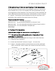
BT 2000 240/300 570/627 3 Construction of the tent 3.1 Pre-assembly of the legs, beams and wind bracings Prepared assembling auxiliaries: Construction tools: Building components: Squared beams Endbeams Crowbar Middlebeams Legs Ridge connectors Safety stanchion for sliding eave connection Pin Ø 20 with washer Ridge pin Ø 16 with washer Equivalent number of wind bracings (see 3.
BT 2000 240/300 570/627 Building parts 20m-tent Pic. 5 14 Spanning the world.
BT 2000 240/300 570/627 Building parts 20m-tent Endbay Pic. 6 15 Spanning the world.
BT 2000 240/300 570/627 Building parts 20m-tent Normal- and bracing bay Pic. 7 16 Spanning the world.
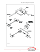
BT 2000 240/300 570/627 Safety pin Sliding eave connection Beam Leg Timber Stopper Sliding eave Windbracing Ring bolt Pic. 8 17 Spanning the world.
BT 2000 240/300 570/627 3.2 Mounting of the components 3.2.1 Connect together each of the left and right end- and middle beams through pushing of the ridge connectors. The placing of timbers makes the mounting easier. Place the pins (pins Ø 16 with washers) to the equivalent borings. Pay attention that the pins fixed tightly (pic. 9). 3.2.2 Push the mounted beams into the receiver of the sliding eave connection to the legs and push them until the limit stop.
BT 2000 240/300 570/627 Ridge pin Beam left Ridge t Timber Beam right Windbracing rope Ring bolt Ridge pin fixed tight Pic. 9 19 Spanning the world.
BT 2000 240/300 570/627 Stanchion pin Ø Beam left Timber Ridge strut Beam right Stanchion pin fixed Pic. 10 20 Spanning the world.
BT 2000 240/300 570/627 Tent’s length up to 40m Windbracing Free fields Windbracing Windbracing Tent’s length over 40 m Free fields Windbracing 2 Free fields (max. 6) Windbracing Pic. 11 21 Spanning the world.
BT 2000 240/300 570/627 3.3 Mounting of the wind bracings Mount the wind bracings (pic. 11). Do not move them out. Mount each of wind bracing to the first and to both last fields of the tent. They must not be more than 6 free fields between the bracings. If more than 6 free fields are built, then an additional wind bracing has to be mounted. See the picture 11 for the mounting of the brace fields.
BT 2000 240/300 570/627 Pic. 12 23 Spanning the world.
BT 2000 240/300 570/627 Pic. 13 24 Spanning the world.
BT 2000 240/300 570/627 4 Erection of the tent You need a self-propelling crane or a fork stacker with telescope for the putting of the tent (see also point 1.2). Protect the dangerous spots during lifting. Do not work under hanging load! 4.1.1 Put the legs of the mounted beams in to the already placed baseplates types B. Adjust the boring, bolt the baseplate and the legs of bay with the pin. Insert the pin from the inside of the tent to outside. Fix tightly the pin with a R-clip. 4.1.
BT 2000 240/300 570/627 purlins of the right and left side of the tent into the endmeans of the placed endbay. For tent types of the roof covers with expander bracing pay attention to the bracing hooks of the eave purlins that they are always facing insides of the tent. Hang up the purlins to the 2. bay with the aid of the mounting fork. Another person will hang the purlins from the mounting drawing case (pic. 14 and 15). 4.1.9 Screw down the free wires of the wind bracing to each respective 4.1.
BT 2000 240/300 570/627 Pic. 14 27 Spanning the world.
BT 2000 240/300 570/627 Purlin Angle Mounting rod Pic. 15 28 Spanning the world.
BT 2000 240/300 570/627 Pic. 16 29 Spanning the world.
BT 2000 240/300 570/627 Gable supportside Giebelstütze - Seite Giebelstütze - Mitte Gable supportmiddle Gable t Gable eave Pin rail- holding Telescoping Connector Gable eave rail Earthanchor Telescoping Foot Baseplate pin R- clip Baseplate Pic 17 30 Spanning the world.
BT 2000 240/300 570/627 Beam Ridge connector Pin Safety bracket Gable Beam Gable eave Leg Pic. 18 31 Spanning the world.
BT 2000 240/300 570/627 4.2 Mounting problems and their causes 4.2.1 The corner- and middle legs do not fit to the baseplate’s receiver: This is usually the result of the inaccurate working in point 2. With the aid of the crowbar try to move the baseplate in the way that the pins could be fixed. If this is not able, check the points from 2.1.2 until 2.1.17. 4.2.2 The baseplate pins cannot be fixed tight: The baseplates are faung the wrong way.
BT 2000 240/300 570/627 Rope Carabine swivel with the opening upwards Buckles to the outside Running position Hanging of pull back rope in Keder running position Leading-in conductor keder Pic. 19 33 Spanning the world.
BT 2000 240/300 570/627 5 Mounting of tent’s covers Before starting the mounting of the tent’s covers, all earth-anchors have to be beaten in and the wind bracings tightened (compare point 4). Use the leading-in conductor for covers. It makes mounting easier and helps to avoid damages to the covers. Do not try to pull in the cover with force. If there is any heavy resistance, pull back another time and try again.
BT 2000 240/300 570/627 5.1.6 Lift the roof cover to the height of the leading-in conductor and feed the right and left keder of the cover through the leading-in conductor into the keder groove of the roof beam, through pulling of the traction cables of the opposite tent’s side (pic. 19). 5.1.7 Pull the two of the traction wires at the same time the roof cover into the roof beam. Pull the cover slowly over the ridge. 5.1.
BT 2000 240/300 570/627 Bracing pipe Roof cover side with angle Bracing pipe Pic. 20 connection profile Bracing pipe Stretch strap ratchet Pic. 21 Roof Clow hooks Thread bracing Pic. 23 Connection Pic. 22 36 Spanning the world.
BT 2000 240/300 570/627 5.2 Stretching of the roof cover (model with fixed tensioning) There are 2 variations to distinguish among the roof covers: a) With fixed bracing aa) –With stretch strap aaa) –With thread bracing b) With rubber tensioning If your tent has the model b) rubber tensioning, then skip this point and go on with the mounting steps of point 5.3.
BT 2000 240/300 570/627 Eave purlin Inside Roof cover Rubber tensioning Eave purlin with rubber tensioning Tensioning hooks Pic. 25 Pic. 24 Roof beam Gable cover Pic. 27 Pic. 26 38 Spanning the world.
BT 2000 240/300 570/627 5.3 Stretching of the roof cover (model with rubber tensioning) There are 2 variations to distinguish among the roof covers: a) With fixed bracing b) With rubber tensioning If your tent has the model a) fixed bracing, then skip this point and go on with the mounting stepts of point 5.2 Work from the outside to the inside by hanging up the elastic chock cord. 5.3.1 Pull the elastic chock cord of the roof cover on one tent side around the eave purlin and hang up into the hooks (pic.
BT 2000 240/300 570/627 5.4 Pulling in the gable covers (gable triangle) The covers for the cover gable are each composed of 2 gable covers, an eyeand a loop side. The inside area of the tent is marked through the sewing of the loops that turns down to the inside and bond resp. this is the overlapping of the sides, which makes a right angle. The outsides have been marked with the signboard RÖDER (if provided) and/or with colour lines (if provided). 5.4.
BT 2000 240/300 570/627 5.5.3 Feed the lower half of the cover and push it fully down. 5.5.4 Hook the cranked hooks into the groove insides of the gable eave rail (eave purlin). 5.5.5 Mount according the points from 5.5.2 until 5.5.4 the respective 2. cover (eye-and loop side). 5.5.6 Cord up both of the covers according the point 5.4.2. 5.5.7 Repeat the points 5.5.2 until 5.5.6 for all the side-and gable walls. Hang up the hooks inside Fix the hooks Pic. 28 41 Spanning the world.
BT 2000 240/300 570/627 5.6 Mounting of the ground rail (if provided). The ground rails for the sidesand gable walls are provided by RÖDER as an accessory. 5.6.1 Feed the ground rails into the ground rails kits of the side curtains (pic. 29). 5.6.2 Push the ground rails on to the 180 mm long flange pin and secure them with a R-clip. 5.6.3 Feed the ground rail for the gable wall into the ground rail kit. 5.6.
BT 2000 240/300 570/627 6 Dismantling For the dismantling of the tent you have to follow the instructions in reverse to the construction. The principle of dismantling: All the covers of the tent ought to be dry before you start folding. After dismantling you have to mark, sort and load all the building components immediately. The using of the peg puller, which is provided as an accessory part, makes the removing of the earth anchors easier. 6.1 Dismantle the ground rails. 6.
BT 2000 240/300 570/627 7 Service notes 7.1 Construction of the tent 7.1.1 The restretching of the wind bracings, treaded bolt connections and roof racings is requisite: - every 3 months (stand-by time) - after hot periods - after a strong gale 7.1.2 Pay attention to the earth-anchors, that is deep seated in a solid position. 7.1.3 Check for deformation or damage. 7.1.4 If there are any damaged parts, then change them immediately with new original spare parts. 7.
BT 2000 240/300 570/627 8 Ratings 8.1 Construction of the tent All the dimensions have been given axial Tent’s length: min. 10,0 m Max.
BT 2000 240/300 570/627 8.