
User`s manual


Table Of Contents
AIR B-Smart BoosterPack – User’s Manual Page 17 of 33
Release Date 11/04/13
USB UART Disconnect DIP Switch (S3)
These DIP switches are used to electrically isolate the USB-UART signals from the
A2541 for applications that require low-power operation. All switch positions should be
set to the same setting (i.e. all ON or all OFF). The default state of all DIP switches is
ON (closed).
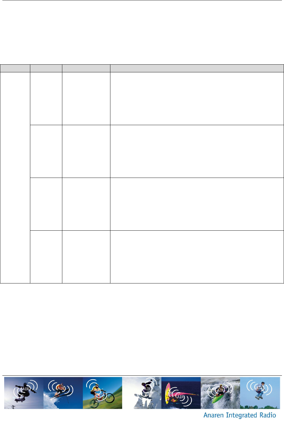
Table 5 – UART DIP Switch Settings (S3)
Switch
Position
Signal Name
Description
S3
1
P1_7/RXD
RXD connect/disconnect.
ON (closed): The radio module RXD pin is connected to
the USB-UART device TXD pin.
OFF (open): The radio module RXD pin is isolated from
the USB-UART device.
2
P1_4/CTS
CTS connect/disconnect.
ON (closed): The radio module CTS pin is connected to
the USB-UART device RTS pin.
OFF (open): The radio module CTS pin is isolated from
the USB-UART device.
3
P1_6/TXD
TXD connect/disconnect.
ON (closed): The radio module TXD pin is connected to
the USB-UART device RXD pin.
OFF (open): The radio module TXD pin is isolated from
the USB-UART device.
4
P1_5/RTS
RTS connect/disconnect.
ON (closed): The radio module RTS pin is connected to
the USB-UART device CTS pin.
OFF (open): The radio module RTS pin is isolated from
the USB-UART device.
MCU User Pushbutton (S4)
Onboard MCU user pushbutton – active low. Duplicate of S2 user pushbutton on MSP-
EXP430G2 LaunchPad. Not populated (default).
MCU Reset (S5)
Onboard MCU hardware reset – active low. Duplicate of S1 reset pushbutton on MSP-
EXP430G2 LaunchPad. Not populated (default).
A2541 Reset (S6)
Radio Module hardware reset – active low.