Model A15/76 Turbidity Monitor Home Office Analytical Technology, Inc. 6 Iron Bridge Drive Collegeville, PA 19426 USA Ph: (800) 959-0299 (610) 917-0991 Fax: (610) 917-0992 Email: sales@analyticaltechnology.com European Office ATI (UK) Limited Unit 1 & 2 Gatehead Business Park Delph New Road, Delph Saddleworth OL3 5DE Ph: 0800-018-4020 + 44 (0) 1457-873-318 Fax: + 44 (0) 1457-874-468 Email: sales@atiuk.
PRODUCT WARRANTY Analytical Technology, Inc. (Manufacturer) warrants to the Customer that if any part(s) of the Manufacturer's products proves to be defective in materials or workmanship within the earlier of 18 months of the date of shipment or 12 months of the date of start-up, such defective parts will be repaired or replaced free of charge. Inspection and repairs to products thought to be defective within the warranty period will be completed at the Manufacturer's facilities in Oaks, PA.
TABLE OF CONTENTS Unpacking .............................................................................................................................. 5 Part 1 - Introduction ................................................................................................................ 6 Specifications .............................................................................................................. 7 Electronics Unit ........................................................................
TABLE OF FIGURES Figure 1 - Turbidity System w/Submersion Sensor ..................................................................... 6 Figure 2 - Panel Mount Monitor Dimensions & Installation .......................................................... 8 Figure 3 - Wall Mount Dimensions & Installation ......................................................................... 9 Figure 4 - Handrail Mounting Assembly ....................................................................................
Unpacking When you receive your Turbidity Monitor, open the shipping package and inspect the contents to be sure that all items have been received. The items shipped will depend on the type of system ordered. The following is a list of items normally supplied with standard flow type systems.
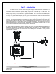
Part 1 - Introduction The Model A15/76 is an on-line monitoring system designed for the continuous measurement of the turbidity of an aqueous stream. It is primarily intended for monitoring turbidity in drinking water or wastewater effluent. The monitor provides display ranges from 0-4.000 NTU up to 0-4000 NTU. The display range used for a given application is user programmable, and an auto-ranging feature allows the display of high turbidity values, even when programmed for low range use.
ATI A15/76 Turbidity Monitor Part 1 - Introduction Specifications Electronics Unit Range: Sensor Type: Accuracy: Linearity: Display: Control Relays: Control Mode: Alarm Relay: Analog Output: user set Operating Conditions: Power: Enclosure: 4/400 NTU (0-4.000, 0-40.00, 0-400.0) 40/4000 NTU (0-40.00, 0-400.0, 0-4000) 9/999 mg/l (or PPM) SiO2 (0-9.999, 0-99.99, 0-999.9) 99/9999 mg/l (or PPM) SiO2 (0-99.99, 0-999.9, 0-9999) 4/400 mg/l PSL (0-4.000, 0-40.00, 0-400.0) 40/4000 mg/l PSL (0-40.00, 0-400.
Part 2 – Mechanical Installation The main installation requirements for ATI’s Turbidity Monitor are mechanical installation, and connection of power to the monitor. Figure 1 on page 5 shows a schematic of a typical installation of a complete system. The monitor should be located near the sensor in order to use the standard 30 foot sensor cable supplied with the system. Longer cable runs can be accommodated using a junction box and additional 7-conductor cable.
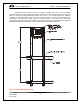
ATI A15/76 Turbidity Monitor Part 2 – Mechanical Installation The optional NEMA 4X wall mount enclosure is a Molded Plastic ABS unit that bolts directly to a wall or other flat surface. The enclosure is supplied with special mounting bracket for convenience in mounting the enclosure. A hinged door on the front of the enclosure provides access to operating controls, and a hinge on the back section for convenience in wiring the unit.
ATI A15/76 Turbidity Monitor Part 2 – Mechanical Installation A special handrail mounting kit (part # 00-0930) is available from ATI for use on standard handrails found around many process tanks. The mounting kit consists of two vertical aluminum supports, which are clamped to the handrail with stainless steel u-bolts. The vertical supports are drilled for connection to horizontal handrails with 18" center to center dimensions.
ATI A15/76 Turbidity Monitor Part 2 – Mechanical Installation The majority of turbidity applications require the use of a flowcell assembly. This method is best when monitoring very low turbidity values, such as filter effluent. The flowcell used with ATI’s turbidity system is designed to eliminate ambient light effects, and to allow sample pressure to be maintained through the flowcell minimizing air bubble formation that can cause erroneous turbidity measurements.
ATI A15/76 Turbidity Monitor Part 2 – Mechanical Installation Figure 7 below shows the recommended installation tubing arrangement for the turbidity system. A 3-way valve is supplied to facilitate calibration of the turbidity monitor. Install the valve as shown below so that turbidity standards can easily be introduced into the flowcell.
ATI A15/76 Turbidity Monitor Part 2 – Mechanical Installation Turbidity sensors may also be installed directly into a flowing pipe system provided that the water does not contain a lot of entrained air. It is best to install the sensor in a vertical pipe section with water flowing upward. This assures that air pockets cannot develop at the sensor. If installed in a horizontal run of pipe, place the sensor at the 3 or 9 o’clock position. Never mount the sensor on the top or bottom of the pipe.
ATI A15/76 Turbidity Monitor Part 2 – Mechanical Installation Figure 9 - Flow "T" Assembly 14 O&M Manual Rev-H (8/11)
ATI A15/76 Turbidity Monitor Part 2 – Mechanical Installation For applications where a submersible turbidity sensor is to be used, a special submersion holder is supplied. This holder is designed to mount on the end of a 1” mounting pipe, with the sensor cable coming up through the center of the pipe. Figure 10 below shows a typical submersion mounting system, including both the submersion holder assembly and ATI’s handrail mounting assembly (part number 000628).
Part 3 – Electrical Connections Wiring connections to the A15/76 are made to the back of the monitor. The terminal blocks on the back of the monitor are pluggable terminals for ease of wiring. Power and alarm relay connections are made to the lower terminal block while sensor and analog output connections are made to the upper block. Refer to Figure 11 below for a detail of the terminal connections on the rear of the turbidity monitor.
ATI A15/76 Turbidity Monitor Part 3 – Electrical Connections DC Powered Monitor Model A15/76 Monitors are available with a DC power option allowing operation on DC voltages between 9 and 36 volts. DC power is connected to terminals 1 and 3 as shown below. Maximum current draw at 12 VDC is approx. 360 mA.
ATI A15/76 Turbidity Monitor Part 3 – Electrical Connections Figure 13 - Remote Sensor Junction Box Wiring 18 O&M Manual Rev-H (8/11)
Part 4 – Start-Up Prior to operation, recheck electrical connections to be sure everything is in accordance with Figure 11 or 11 in the previous section. If everything is in order, power may be applied. When power is turned on, the display will come up with a program and version number, which will remain on the display for a few seconds. The display will then change to a display of the pH value and an indication of the status of control relays.
ATI A15/76 Turbidity Monitor Part 4 – Startup Front Panel Lock The key switches on the front panel of the monitor can be used for both changing the display and for calibrations and setpoint adjustments. When the monitor is shipped from ATI, all functions are accessible. However, the adjustment and calibration functions can be locked in order to prevent unauthorized adjustments to the instrument.
Part 5 - Configuration The electronics for the Turbidity system are designed to be as flexible as possible. A number of programming functions are provided in the CONFIGURATION menu and are protected by an access number, which must be entered to allow changes in these settings. Some settings are for factory use only, while others are used for customer selection of certain operating parameters. Press the MODE key until the display reads CONFIGURATION and then press CAL.
ATI A15/76 Turbidity Monitor Part 5 – Configuration 8. Small S RT: 120s This routine sets the damping value for small changes in turbidity values. The value for this damping factor is set at a fairly high value to eliminate fluctuations in the reading caused by occasional bubbles or other sample anomalies. As with #7 above, this setting can be adjusted between 5 seconds and 220 seconds to provide the desired damping of small changes. 9.
ATI A15/76 Turbidity Monitor Part 5 – Configuration 19. AL TYPE: CONT. This routine allow definition of the operation of the alarm relay. The alarm relay C can be programmed for either continuous or flash operation. In continuous mode, an alarm will cause the relay coil to change state and stay in that position. In “flash” mode, the relay coil will toggle so that anything connected through the relay will alternate from on to off.
Part 6 - Operation Turbidity monitors will start to measure aqueous samples as soon as power is applied. Calibration of a turbidity system is normally required at start-up, but factory settings are likely to be fairly accurate, so it is often OK to start up the montor without adjustment. Calibration requires adjustment of both the zero and span of the instrument.
ATI A15/76 Turbidity Monitor Part 6 – Operation Manual Low Level Offset Adjustment While not normally required, the A15/76 contains an adjustment routine that allows the operator to adjust the lower end of the measuring range to match values obtained by an alternate measuring device. This routine should only be used when adjusting turbidity values below about 0.200 NTU. To offset a low level turbidity value, follow the procedure below. 1.
ATI A15/76 Turbidity Monitor Part 6 – Operation 1. Refer to Figure 7 on page 11. The 3-way valve supplied with the flowcell provides a convenient port for draining the flowcell and introducing a calibration standard into the flowcell. As part of the system, a 60 cc syringe and 18” of silicon tubing is provided for use in feeding standard into the flowcell. 2. Prior to feeding standard, the flowcell must be drained. Turn the yellow valve handle so that the OFF position is facing the sample inlet tube.
ATI A15/76 Turbidity Monitor Part 6 – Operation Controls & Alarm Outputs The A15/76 Turbidity Monitor is equipped with three relay outputs. Two of these outputs are designated control relays and the third is designated as an alarm relay. These output relays may be used in a variety of ways, and the function of each relay is programmable by the operator. Relay output wiring is made at the rear of the monitor as shown in the diagram on page 14.
ATI A15/76 Turbidity Monitor Part 6 – Operation The alarm relay will always activate if either a high or low conductivity condition exists. The setpoints for this alarm are programmable. If an alarm condition is detected, the relay will activate and the LCD display will flash "ALARM: MEASURE”. The default values are 0 for low alarm and display range full scale for high alarm. To program the Alarm Relay for different low and high setpoints, proceed as follows: 1.
ATI A15/76 Turbidity Monitor Part 6 – Operation Auto/Manual/ Simulate Operating Mode The A15/76 will normally operate in AUTO mode. In this mode, the monitor will display turbidity values and indicate any alarms as described previously. However, a “Manual Mode” and a “Simulate Mode” of operation is selectable in order to allow the user to activate the A and B relays manually for test purposes or to manually ramp the 4-20 mA output value up and down for testing external devices.
ATI A15/76 Turbidity Monitor Part 6 – Operation Check Signal Display The check signal display (D3, page 16), is a display routine used to provide an indication of the condition of the sensor. The check signal value will decrease as any types of deposits foul the sensor. If the sensor becomes dry due to loss of sample flow, the check signal value will go to a high number. In normal operation with a clean sensor, the check signal value will be around 100%.
Part 7 - Maintenance The A15/76 Turbidity Monitor will generally provide unattended operation over long periods of time. With proper care, the system should continue to provide measurements indefinitely. For reliable operation, maintenance on the system must be done on a regular schedule. Keep in mind that preventive maintenance on a regular schedule is much less troublesome than emergency maintenance that always seems to come at the wrong time.
SPARE PARTS LIST PART NO. DESCRIPTION 00-0804 03-0181 63-0036 63-0037 63-0038 00-1491 00-0726 31-0038 00-0930 00-0628 44-0153 44-0159 44-0164 44-0270 Complete turbidity monitor electronics, panel mount NEMA 4X enclosure assembly Turbidity sensor Turbidity sensor cable, 30 ft.