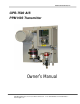
Advanced Instruments, Inc. GPR-7500 AIS PPM H2S Transmitter Owner’s Manual 2855 Metropolitan Place, Pomona, California 91767 USA ♦ Tel: 909-392-6900, Fax: 909-392-3665, email: info@aii1.
Advanced Instruments, Inc.
Advanced Instruments, Inc. 1. Introduction Your new hydrogen sulfide transmitter incorporates an advanced electrochemical sensor specific to hydrogen sulfide along with state-of-the-art digital electronics designed to give you years of reliable precise measurements of hydrogen sulfide in a variety of industrial applications.
Advanced Instruments, Inc. 2.
Advanced Instruments, Inc. 3. Maintenance Serviceability: Except for replacing the hydrogen sulfide sensor, there are no parts inside the transmitter for the operator to service. Only trained personnel with the authorization of their supervisor should conduct maintenance. H2S Sensor: DO NOT open the sensor. The sensor contains a corrosive liquid electrolyte that could be harmful if touched or ingested, refer to the Material Safety Data Sheet contained in the Owner’s Manual appendix.
Advanced Instruments, Inc. temperature of 77°F/25°C and pressure of1 atmosphere in “normal” applications. Deviations from standard 0 conditions will affect the life of the sensor (temperature higher than 77 C and pressure less than atmospheric would cause a reduction in the sensor life). Accuracy and Calibration: Refer to section 5 Operation.
Advanced Instruments, Inc. Application, Positive-Pressure A flow indicator with integral metering valve positioned upstream of the sensor is recommended for controlling the sample flow rate between 1-5 SCFH. If a separate flow control valve and a flow indicator is used, position flow control valve upstream of the sensor and position a flow indicator downstream of the sensor.
Advanced Instruments, Inc. 4.
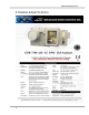
Advanced Instruments, Inc. 5. Operation Principle of Operation The GPR-7500AIS H2S Transmitter incorporates a variety of advanced electrochemical sensors. These sensors are very specific to H2S and generate an electrical signal proportional to the amount of H2S present in a gas stream. The selection of a particular type of sensor depends on the maximum concentration of H2S contents in the sample stream. Consult the factory for recommendation. The transmitter is configured in two sections.
Advanced Instruments, Inc. Advanced Electrochemical Sensor Technology All electrochemical sensors driven by a bias potential (three electrode configuration) function on the same principle and are specific to a certain gas. They measure the partial pressure of the target gas from low PPM to up to 1% levels in air, inert gases and gaseous hydrocarbons.
Advanced Instruments, Inc. pressure on the sensor will alter the output of the sensor and unless the sensor is calibrated under the same analysis conditions, a significant error in measurements will occur. For positive sample pressure applications, the sample pressure must be regulated by using a pressure regulator.
Advanced Instruments, Inc. Mounting of the Transmitter The GPR-7500AIS transmitter consists of two interconnected enclosures (without the optional sample conditioning system and panel) and measures 8”H x 15-3/4”W x 7”D. This configuration is designed to be mounted directly to any flat vertical surface, wall or bulkhead plate by using eight (4) of the appropriate screws.
Advanced Instruments, Inc. Gas Connections The GPR-7500AIS with its standard flow through configuration is designed for positive pressure samples and requires connections for an incoming sample and an outgoing vent line. Zero and span inlet ports are offered as part of the optional sample systems. The user is responsible for calibration gases and other required components, see below. Procedure Caution: Do not change the factory setting until instructed to do in this manual. 1. 2. 3. 4. 5. 6. 7. 8. 9.
Advanced Instruments, Inc. Note: If equipped with optional H2S scrubber, the H2S from the sample gas will be removed by the scrubbing material. The scrubbing material changes its color from purple to light pale. Replace scrubbing material when 2/3 of the material had changed its color from purple to pale.
Advanced Instruments, Inc. Electrical Connections The Incoming power, alarm relays, and signal output connections are made to terminal blocks mounted on a PCB located in the explosion proof enclosure. Do not supply voltage above the noted value in this manual and noted near the power input terminal of the analyzer. The PCB in the explosion proof enclosure contains a power limiting intrinsic safety barrier that limit the total power available at the PCB electronics mounted in the general purpose enclosure.
Advanced Instruments, Inc. Hazardous Area Installation The GPR-7500AIS may be installed in a hazardous area when adhered to the recommended installation procedure. Power Input A 12-28 VDC or 100/230 VAC power supply with a shielded power cable is recommended. The power cable to the Ex enclosure must be supplied through a conduit approved for use in hazardous area. Secure the wires to the power input terminal block by using the integral screws of the terminal block. Do not substitute terminal screws.
Advanced Instruments, Inc. Note: The male and female power terminals snap together, making it difficult to detach them when connecting the shield to the ground. However, after connecting the shield, ensure that the male terminal is fully inserted and secured into the female terminal block. Installation of H2S Sensor The GPR-7500AIS Oxygen Transmitter is equipped with SS sensor housing. This housing offers ease of replacement of sensor and at the same time prevents any leakage into the system.
Advanced Instruments, Inc. Span Gas Preparation Note: The GPR-7500AIS can be calibrated by using a certified span gas, preferably 50-80% of the full scale of the least sensitive range. After initial calibration, subsequent calibration should be carried out by using a span gas between 50 to 80% of the range of interest or one range above the range of interest. Caution: Do not inhale the H2S span gas.
Advanced Instruments, Inc. Establishing Power to Electronics Once the two power input wires of the shielded cable are properly connected to the terminals inside the Ex enclosure as described above, connect the other end of the two wires to a suitable 12-24 VDC power source such as a battery, PLC, DCS, etc. The digital display responds instantaneously.
Advanced Instruments, Inc. This screen shows various options available. You can use the UP and DOWN arrow key to move the cursor and highlight the desired function. After moving the cursor to the desired function, press ENTER to access that function. Range Selection The GPR-7500 AIS transmitter is equipped with three (3) standard measuring ranges (see specification) and provides users with a choice of sampling modes.
Advanced Instruments, Inc. 4. Advance the reverse shade cursor using the ARROW keys to highlight the desired MANUAL RANGE. 5. Press the ENTER key to select the highlighted menu option. The following display appears with the range selected and oxygen concentration of the sample gas: 12 PPM Manual Sampling 0-500 PPM Range 76 F LO1 0 PPM 6. 97 Kpa HI 40 PPM If the value of H2S goes above the full scale range selected, display will not shift to the next higher range.
Advanced Instruments, Inc. The maximum zero offset of every transmitter is checked prior to shipment. However, due to the fact that the factory sample system conditions differ from that of the user, no ZERO OFFSET adjustment is made at the factory Typical offset seen is less than 0.5-1 PPM. Therefore, for most applications, a Zero calibration is not required. However, ZERO calibration option has been provided to allow the user to precisely measure H2S concentration at the very low levels (less than 0.
Advanced Instruments, Inc. offset does not exceed 50% of the lowest range, this indicates that the integrity of the sensor, the analyzer/transmitter sample system and the sample line bringing in the sample gas is maintained. 1. Access the MAIN MENU by pressing the MENU key. 2. Advance the reverse shade cursor using the ARROW keys to highlight CALIBRATION. 3. Press the ENTER key to select the highlighted menu option.
Advanced Instruments, Inc. 2. Advance the reverse shade cursor using the ARROW keys to highlight CALIBRATION. 3. Press the ENTER key to select the highlighted menu option. The following displays appear: MAIN MENU CALIBRATION AUTO SAMPLE SPAN CALIBRATE MSNUAL SAMPLE ZERO CALIBRATE CALIBRATION DEFAULT SPAN CONFIG ALARMS DEFAULT ZERO BYPASS ALARMS OUTPUT SPAN OUTPUT ZERO 4. Advance the reverse shade cursor using the ARROW keys to highlight DEFAULT ZERO. 5.
Advanced Instruments, Inc. 100 OUTPUT ZERO OFFSET PRESS UP OR DOWN TO CHANGE VALUE ENTER TO SAVE MENU TO RETUE 6. The default setting of 100 illustrates no adjustment to the 4 mA signal. Adjust the initial value to above 100 to increase the analog signal value or decrease it below 100 to decrease the analog signal. 7. Press the ENTER key to advance the underline cursor right or press the MENU key to advance the underline cursor left to reach to the desired digit. 8.
Advanced Instruments, Inc. 8. After selecting the SPAN CALIBRATION, the following displays appear: 0000 PPM PRESS UP OR DOWN TO CHANGE VALUE ENTER TO SAVE MENUE TO ABORT 9. Press the ENTER key to advance the underline cursor right or press the MENU key to advance the underline cursor left to reach to the desired digit of the alarm value. 10. Repeat until the complete span value has been entered and press ENTER. The following display will appear.
Advanced Instruments, Inc. MAIN MENU CALIBRATION AUTO SAMPLE SPAN CALIBRATE MANUAL SAMPLE ZERO CALIBRATE CALIBRATION DEFAULT SPAN CONFIG ALARMS DEFAULT ZERO BYPASS ALARMS OUTPUT SPAN OUTPUT ZERO 4. Advance the reverse shade cursor using the ARROW keys to highlight DEFAULT SPAN. 5. Press the ENTER key to select the highlighted menu option.
Advanced Instruments, Inc. 100.0 OUTPUT SPAN OFFSET PRESS UP OR DOWN TO CHANGE VALUE ENTER TO SAVE MENU TO RETURN 6. The default setting of 100 illustrates no adjustment to the analog output signal. Adjust the initial value to above 100 to increase the 20 mA analog signal value or decrease it below 100 to decrease the 20 mA analog signal. 7.
Advanced Instruments, Inc. 14. If the transmitter is equipped with an optional integral sampling pump (positioned downstream of the sensor) and a flow control metering valve (positioned upstream of the sensor), completely open the flow control metering valve to avoid drawing a vacuum on the sensor and placing an undue burden on the pump Setting Alarms The analyzer is equipped with two programmable alarm relays.
Advanced Instruments, Inc. 6. Maintenance Generally, replacing the sensor periodically or replacing filter element of the coalescing filter is the extent of the maintenance requirements of this transmitter. Serviceability: Except for replacing the sensor, there are no parts inside the transmitter for the operator to service. Only trained personnel with the authorization of their supervisor should conduct maintenance. 7. Spare Parts Recommended spare parts for the GPR-1500 IS Oxygen Transmitter: Item No.
Advanced Instruments, Inc. 8.
Advanced Instruments, Inc.
Advanced Instruments, Inc. 9. Warranty The design and manufacture of GPR Series oxygen transmitters/analyzers, monitors and oxygen sensors are performed under a certified Quality Assurance System that conforms to established standards and incorporates state of the art materials and components for superior performance and minimal cost of ownership.
Advanced Instruments, Inc. 10. MSDS – Material Safety Data Sheet Product Identification Product Name H2S sensor Series - GPR Synonyms Electrochemical Sensor Manufacturer Advanced Instruments Inc., 2855 Metropolitan Place, Pomona, CA 91767 USA Emergency Phone Number 909-392-6900 Preparation / Revision Date January 1, 1995 Notes H2S sensors are sealed, contain protective coverings and in normal conditions do not present a health hazard. Information applies to electrolyte unless otherwise noted.
Advanced Instruments, Inc. Unusual Fire and Explosion Hazards Not applicable Reactivity Data Stability Stable Conditions Contributing to Instability None Incompatibility Acid = Avoid contact with strong bases Hazardous Decomposition Products Acid = Emits toxic fumes when heated Conditions to Avoid Heat above 70 degree C Spill or Leak Steps if material is released Sensor is packaged in a sealed plastic bag, check the sensor inside for electrolyte leakage.
Advanced Instruments, Inc.