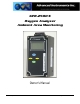
GPR-2500 S Oxygen Analyzer Ambient Area Monitoring Owner’s Manual 2855 Metropolitan Place, Pomona, CA 91767 USA ♦ Tel: 909-392-6900, Fax: 909-392-3665, e-mail: info@aii2.com, www.aii2.
Table of Contents Introduction 1 Quality Control Certification 2 Safety 3 Features & Specifications 4 Operation 5 Maintenance 6 Spare Parts 7 Troubleshooting 8 Warranty 9 Material Safety Data Sheets 10 2
1 Introduction Your new oxygen analyzer incorporates an advanced electrochemical sensor specific to oxygen along with state-ofthe-art digital electronics designed to give you years of reliable precise oxygen measurements in variety of industrial oxygen applications. The GPR-2500S is generally used to monitor the oxygen content of a confined space or control room occupied by humans for a deficiency of oxygen.
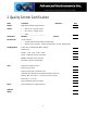
2 Quality Control Certification Date: Customer: Model GPR-2500S Ambient Oxygen Monitor Sensor ( ) GPR-11-32-4 Oxygen Sensor ( ) XLT-11-24-4 Oxygen Sensor ( ) Other _____________________ Serial Nos.: Monitor: Accessories: Owner’s Manual Configuration: Order No.
3 General Safety & Installation General This section summarizes the essential precautions applicable to the GPR-2500S Ambient Oxygen Monitor. Additional precautions specific to individual monitor are contained in the following sections of this manual. To operate the monitor safely and obtain maximum performance follow the basic guidelines outlined in this Owner’s Manual.
Installation Gas Sample Stream: Ensure the gas stream composition of the application is consistent with the specifications and review the application conditions before initiating the installation. Consult the factory to ensure the sample is suitable for analysis. Note: In natural gas applications such as extraction and transmission, a low voltage current is applied to the pipeline itself to inhibit corrosion. As a result, electronic devices can be affected unless adequately grounded.
Analyzers designed for flowing samples under positive pressure or pump vacuum (for samples at atmospheric or slightly negative atmospheres) that does not exceed 14” water column are equipped with bulkhead tube fitting connections on the side of the unit (unless otherwise indicated, either fitting can serve as inlet or vent) and are intended to operate at positive pressure regulated to between 5-30 psig although their particular rating is considerably higher.
¾ ¾ ¾ wipe away. If the analyzer is equipped with an optional integral sampling pump (positioned downstream of the sensor) and a flow control metering valve (positioned upstream of the sensor), completely open the flow control metering valve to avoid drawing a vacuum on the sensor and placing an undue burden on the pump. Calibrate ambient area monitors with a certified span gas/ Avoid calibration of ambient area monitors with the surrounding atmosphere unless assured the oxygen content is 20.9%.
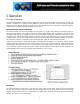
5 Operation Principle of Operation The GPR-2500S Ambient Oxygen Monitor incorporates a variety of advanced galvanic fuel cell type sensors. The monitor is configured in a general purpose NEMA 4X rated enclosure and meets the intrinsic safety standards required for use in Class 1, Division 1, Groups A, B, C, D hazardous areas when operated in conjunction with the manufacturer’s recommended optional intrinsic safety barriers.
Sample oxygen is analyzed very accurately. Response time of 90% of full scale is less than 10 seconds (actual experience may vary due to the integrity of sample line connections, dead volume and flow rate selected) on all ranges under ambient monitoring conditions. Sensitivity is typically 0.5% of full scale low range. Oxygen readings may be recorded by an external device via the 0-1V signal output jack.
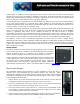
5. The monitors design provides protection from RFI that is maintained by leaving specific mating areas of the enclosure unpainted to maintain conductivity the gasket, top and bottom sections of the enclosure. These unpainted areas are protected by gaskets and contribute to maintaining the NEMA 4 rating. Do not paint these areas. Painting will negate the RFI protection. 6. As described below the power connection is made through the junction box on the left side of the enclosure.
4. FITN-1029 Connector, Barbed Tubing 5. A-2344 Calibration Flow Through Adapter (Calibration use only) 6. A-2781 Nut Sensor Retaining Electrical Connections Remove the front cover of the junction box located on left side of the monitors by removing the four (4) screws securing the cover and set them aside for reinstallation. To assure proper grounding, connect the 4-20mA signal output to the external device (PLC, DCS, etc.) before attempting any zero or span adjustments.
18,500 ft. – 16 AWG 29,500 ft. – 14 AWG Connections – Optional Intrinsic Safety Barrier: Non-hazardous area: Barrier terminals (1), (2) Hazardous area: Barrier terminals (3), (4) Direct measurement of 4-20mA: Reference (C1), connect the current measuring device at terminal (2) of the barrier and the negative (-) terminal from the power source as shown below.
When used in conjunction with the optional MTL 702, third party certified, intrinsic safety barriers, the design of the GPR-2500S Ambient Oxygen Monitors meet recognized standards as intrinsically safe for operation in Class I, II, III; Division I, II; Groups A-G hazardous areas. Note: Locate the optional intrinsic safety barrier as close to the power source in the non-hazardous area as possible.
Installing the Oxygen Sensor The GPR-2500S ppm Ambient Oxygen Monitor is normally equipped with an integral oxygen sensor. It has been tested and calibrated by the manufacturer prior to shipment and are fully operational from the shipping container. However, when the application requires a remote sensor (external to the electronics enclosure) or other special circumstances, the oxygen sensor will be packaged separately and must be installed prior to operating the monitor.
7. Assure the keyway registration of the female plug on the cable and male receptacle on the sensor match up. 8. Push the female plug (including the knurled lock nut) molded to the cable into the male receptacle attached to the new sensor. 9. Screw the knurled lock nut attached the cable onto to the male connector attached to the sensor, tighten finger tight plus ¼ turn. 10. Replace the front cover of the monitor and ensure that the gasket is replaced as well to maintain CE approval and NEMA 4 rating. 11.
Span Gas Preparation Caution: Do not contaminate the span gas cylinder when connecting the regulator. Bleed the air filled regulator (faster and more reliable than simply flowing the span gas) before attempting the initial calibration of the instrument. Required components: ¾ Certified span gas cylinder with an oxygen concentration, balance nitrogen, approximating 80% of the full scale range above the intended measuring range. ¾ Regulator to reduce pressure to between 5 and 30 psig.
3. Review Span Gas Preparation section below – regulate the pressure and control the flow rate as directed. 4. Caution: When ambient monitoring of oxygen deficiency in a confined space or room do not calibrate the unit in the atmosphere to be monitored. Use a certified span gas of a known oxygen concentration approximating 20.9% oxygen balance nitrogen or clean compressed air. 5.
Note: The monitor display defaults to the sampling mode when 30 seconds elapses without user interface. 20.9% MANUAL SAMPLING 25% RANGE 24.5 C 100 KPA Menu Navigation The four (4) pushbuttons located on the front of the monitor operate the micro-processor: ¾ green ENTER (select) ¾ yellow UP ARROW ¾ yellow DOWN ARROW ¾ blue MENU (escape) Main Menu Access the MAIN MENU by pressing the MENU key: MAIN MENU AUTO SAMPLE MANUAL SAMPLE CALIBRATE 24.
Press the ENTER key to select the highlighted menu option. The display returns to the sampling mode WHEN THE SENSOR IS EXPOSED TO AMBIENT AIR: 20.9% MAIN MENU AUTO SAMPLE MANUAL SAMPLE CALIBRATE 24.5 C AUTO SAMPLING 25% RANGE 100 KPA 24.5 C 100 KPA The display will shift to the next higher range when the oxygen reading (actually the sensor’s signal output) exceeds 99.9% of the upper limit of the current range.
The display will not shift automatically. Instead, when the oxygen reading (actually the sensor’s signal output) exceeds 110% of the upper limit of the current range an OVER RANGE warning will be displayed. 27.0% OVERRANGE MANUAL SAMPLING 25% RANGE 24.
Zero Calibration In theory, the oxygen sensor produces no signal output when exposed to an oxygen free sample gas.
Press the ENTER key to calibrate or MENU key to abort and return to SAMPLING mode. 0.000 PPM ZERO CALIBRTION ENTER TO CALIBRATE MENU TO ABORT Allow approximately 60 seconds for the calibration process while the processor determines whether the signal output or reading has stabilized within 60% of the full scale low range.
MAIN MENU CALIBRATION AUTO SAMPLE MANUAL SAMPLE CALIBRATE 24.5 C >>> 100 KPA SPAN CALIBRATE ZERO CALIBRATE DEFAULT SPAN DEFAULT ZERO 24.5 C 100 KPA Span Calibration Maximum drift from calibration temperature is approximately 0.11% of reading per °C. The monitor has been calibrated at the factory. However, in order to obtain reliable data, the monitor must be calibrated at the initial start-up and periodically thereafter.
MAIN MENU CALIBRATION AUTO SAMPLE MANUAL SAMPLE CALIBRATE 24.5 C >>> 100 KPA SPAN CALIBRATE ZERO CALIBRATE DEFAULT SPAN DEFAULT ZERO 24.5 C 100 KPA Manual Span The user must ascertain that the oxygen reading (actually the sensor’s signal output) has reached a stable value within the limits entered below before entering the span adjustment. Failure to do so will result in an error. Preparation - Required components: Refer to Installing Span Gas section above.
Press the ENTER key to select the highlighted menu option. The following displays appears: MAIN MENU MANUAL RANGE AUTO SAMPLE MANUAL SAMPLE CALIBRATE >>> 24.5 C 25% 10% 5% 1% 100 KPA Advance the reverse shade cursor using the ARROW keys to highlight the desired RANGE. Press the ENTER key to select the highlighted menu option. The following display appears with the range selected and oxygen concentration of the sample gas: 20.9% MANUAL SAMPLING 25% RANGE 24.
Press the ENTER key to select the SPAN CALIBRATE option. Note: A span gas concentration above 1000 ppm dictates the selection of the PERCENT option. Advance the reverse shade cursor using the ARROW keys to highlight the desired GAS CONCENTRATION. Press the ENTER key to select the highlighted menu option. GAS CONCENTRATION PERCENT PPM The following displays appear: 00.00 % 20.
20.9% MANUAL SAMPLING 25% RANGE 24.5 C 100 KPA If the calibration is unsuccessful, return to the SAMPLING mode with span gas flowing through the monitor, make sure the reading stabilizes and repeat the calibration before concluding the equipment is defective. If the calibration is successful, remove the flow through adapter to expose the sensor to the ambient air. Wait 5 minutes to ensure the reading is stable and proceed to sampling.
6 Maintenance Generally, cleaning the electrical contacts or replacing filter elements is the extent of the maintenance requirements of this monitor. Sensor Replacement Periodically, the oxygen sensor will require replacement. The operating life is determined by a number of factors that are influenced by the user and therefore difficult to predict. The Features & Specifications define the normal operating conditions and expected life of the standard sensor utilized by the GPR-2500S monitor.
10. Replace the front cover of the monitor and ensure that the gasket is replaced as well to maintain CE approval and NEMA 4 rating. 11. Tighten the four (4) screws to secure the front cover. 12. Connect the gas lines, vent line first, as previously described. 13. Proceed to calibration. Procedure - Remote Oxygen Sensor: 1. Locate Item #1 sensor cable. 2. Loosen the knurled lock nut attached to the sensor cable and pull the attached female plug out of the male connector attached to the sensor 3.
7 Spare Parts Recommended spare parts for the GPR-2500S Ambient Oxygen Monitor: Item No. Description GPR-11-32-4 Oxygen Sensor Other spare parts: Item No.
8 Troubleshooting Symptom Possible Cause Recommended Action reflect Sensor was not calibrated at the pressure, flow rate and temperature anticipated in the sample gas stream Recalibrate the monitor Oxygen reading drifts toward zero or significant number of turns of the span control adjustment is required to calibrate the monitor. Indication sensor is nearing the end of its useful life Replace sensor, Maintenance.
9 Warranty Policy What is covered: Any defect in material and workmanship from normal use in accordance with the Owner’s Manual. This warranty applies to all monitor purchased worldwide. Advanced Instruments Inc. reserves the right in its sole discretion to invalidate this warranty if the serial number does not appear on the monitor. For how long: One year from shipment by manufacturer or purchase from a distributor with proof of purchase.
What is not covered: This warranty does not cover installation; defects resulting from accidents; damage while in transit to our service location; damage resulting from alterations, misuse or abuse; lack of proper maintenance; unauthorized repair or modification of the monitor; affixing of any attachment not provided with the monitor; fire, flood, or acts of God; or other failure to follow the Owner’s Manual. Sole Warranty This warranty is the only one we will give on your Advanced Instruments Inc.
10 Material Safety Data Sheet ( MSDS ) Product Identification Product Name Oxygen Sensor Models CAD, GPR, PSR, SAF, 67013 Synonyms Galvanic Fuel Cell, Electrochemical Transducer Manufacturer Analytical Industries Inc. 2855 Metropolitan Place, Pomona, CA 91767 USA Emergency Phone Number 909-392-6900 Preparation / Revision Date January 1, 1995 Notes Oxygen sensors are sealed, contain protective coverings and in normal conditions do not present a health hazard.
General Requirements Use Potassium Hydroxide - electrolyte, Lead - anode Handling Rubber or latex gloves and safety glasses Storage Indefinitely Fire and Explosion Data Flash and Fire Points Not applicable Flammable Limits Not flammable Extinguishing Method Not applicable Special Fire Fighting Procedures Not applicable Unusual Hazards Not applicable Fire and Explosion Reactivity Data Stability Conditions Instability Stable Contributing to Incompatibility Hazardous Products None Avoid
Skin Electrolyte is corrosive and skin contact could result in a chemical burn. Inhalation Liquid inhalation is unlikely. Symptoms Eye contact - burning sensation; Skin contact - soapy slick feeling. Medical Conditions Aggravated None Carcinogenic Reference Data NTP Annual Report on Carcinogens - not listed; LARC Monographs not listed; OSHA - not listed Other Lead is listed as a chemical known to the State of California to cause birth defects or other reproductive harm.
Product Identification Product Name Oxygen Sensor Models XLT Synonyms Galvanic Fuel Cell, Electrochemical Transducer Manufacturer Analytical Industries Inc. 2855 Metropolitan Place, Pomona, CA 91767 USA Emergency Phone Number 909-392-6900 Preparation / Revision Date January 1, 1995 Notes Oxygen sensors are sealed, contain protective coverings and in normal conditions do not present a health hazard. Information applies to electrolyte unless otherwise noted.
Fire and Explosion Data Flash and Fire Points Not applicable Flammable Limits Not flammable Extinguishing Method Not applicable Special Fire Fighting Procedures Not applicable Unusual Fire and Explosion Hazards Not applicable Reactivity Data Stability Stable Conditions Contributing to Instability None Incompatibility Avoid contact with strong bases Hazardous Decomposition Products Emits toxic fumes when heated Conditions to Avoid Heat Spill or Leak Steps if material is released Sensor i
Emergency First Aid Ingestion Do not induce vomiting; Give plenty of cold water or if available milk; Seek medical attention immediately. Skin Contact Wash affected area repeatedly with plenty of water; Remove contaminated clothing; If burning persists, seek medical attention. Eye Contact Flush repeatedly with plenty of water for at least 15 minutes; Seek medical attention immediately. Inhalation Liquid inhalation is unlikely.