GPR-2500A Oxygen Transmitter Owner’s Manual 2855 Metropolitan Place, Pomona, CA 91767 USA ♦ Tel: 909-392-6900, Fax: 909-392-3665, e-mail: info@aii2.com, www.aii2.
Table of Contents Introduction 1 Quality Control Certification 2 Safety 3 Features & Specifications 4 Operation 5 Maintenance 6 Spare Parts 7 Troubleshooting 8 Warranty 9 Material Safety Data Sheets 10 Drawings A/R 2
1 Introduction Your new oxygen transmitter incorporated an advanced electrochemical sensor specific to oxygen along with stateof-the-art digital electronics designed to give you years of reliable precise oxygen measurements in variety of industrial oxygen applications. To obtain maximum performance from your new oxygen transmitter, please read and follow the guidelines provided in this Owner’s Manual.
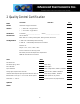
2 Quality Control Certification Date: Customer: Model: GPR-2500A Oxygen Transmitter Sensor: ( ) GPR-11-32-4 Oxygen Sensor ( ) XLT-11-24-4 oxygen Sensor Order No.: Serial Nos.
3 Safety General This section summarizes the essential precautions applicable to the GPR-2500A Oxygen Transmitter. Additional precautions specific to individual transmitter are contained in the following sections of this manual. To operate the transmitter safely and obtain maximum performance follow the basic guidelines outlined in this Owner’s Manual. Caution: This symbol is used throughout the Owner’s Manual to Caution and alert the user to recommended safety and/or operating guidelines.
Maintenance Serviceability: Except for replacing the oxygen sensor, there are no parts inside the transmitter for the operator to service. Only trained personnel with the authorization of their supervisor should conduct maintenance. Oxygen Sensor: DO NOT open the sensor. The sensor contains a corrosive liquid electrolyte that could be harmful if touched or ingested, refer to the Material Safety Data Sheet contained in the Owner’s Manual appendix.
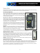
5 Operation Principle of Operation The GPR-2500A oxygen transmitter incorporates a variety of advanced galvanic fuel cell type sensors. The transmitter is a compact efficient package configured with the oxygen sensor and separate circuits boards for signal processing and terminals for incoming power, power supply, signal output and alarm relay contacts housed in a general purpose NEMA 4X rated enclosure.
Pressure & Flow All electrochemical oxygen sensors respond to partial pressure changes in oxygen. The inlet pressure must always be higher than the pressure at the outlet vent which is normally at atmospheric pressure. Flow Through Configuration: The sensor is exposed to sample gas that must flow or be drawn through metal or Tygon tubing inside the transmitter.
To avoid erroneous oxygen readings and damaging the sensor: ¾ Do not place your finger over the vent (it pressurizes the sensor) to test the flow indicator when gas is flowing to the sensor. Removing your finger (the restriction) generates a vacuum on the sensor and may damage the sensor (voiding the sensor warranty).
Calibration & Accuracy Single Point Calibration: As previously described the galvanic oxygen sensor generates an electrical current sensor exhibiting an absolute zero, e.g. the sensor does not generate a current output in the absence of oxygen. Given these linearity and absolute zero properties, single point calibration is possible. Pressure: Because sensors are sensitive to the partial pressure of oxygen in the sample gas their output is a function of the number of molecules of oxygen 'per unit volume'.
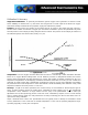
Example: As illustrated by Graph A any error, play in the multi-turn span pot or the temperature compensation circuit, during a span adjustment at 20.9% (air) of full scale range would be multiplied by a factor of 4.78 (100/20.9) if used for measurements of 95-100% oxygen concentrations. Conversely, an error during a span adjustment at 100% of full scale range is reduced proportionately for measurements of lower oxygen concentrations.
¾ Pressure & Flow: As described above. ¾ Moisture & Particulates: Prevent water and/or particulates from entering the sample system. They can clog the tubing and damage the optional components such as pumps, scrubbers or sensors. Installation of a suitable coalescing or particulate filter is required to remove condensation, moisture and/or particulates from the sample gas to prevent erroneous analysis readings and damage to the sensor or optional components.
Gas Connections: The GPR-2500A with its standard flow through configuration is designed for positive pressure samples and requires connections for incoming sample and outgoing vent lines. The user is responsible for calibration gases and the required components, see below. Flow rates of 1-5 SCFH cause no appreciable change in the oxygen reading.
7. Assure the keyway registration of the female plug on the cable and male receptacle on the sensor match up. 8. Push the female plug (including the knurled lock nut) molded to the cable into the male receptacle attached to the new sensor. 9. Screw the knurled lock nut attached the cable onto to the male connector attached to the sensor, tighten finger tight plus ¼ turn. 10. Replace the front cover of the transmitter and ensure that the gasket is replaced as well to maintain CE approval and NEMA 4 rating.
Electrical Connections: Electrical connections to the GPR-2500A are made at two different locations within the transmitters. Power requirements consist of a two wire shielded cable and a 12-36V DC with negative ground power supply. Incoming power is connected via a terminal strip found in the junction box on the left side of the GPR-2500A enclosure. Caution: The integral 4-20mA converter is internally powered and does not require external power.
The 4-20mA signal output, power fail, alarm relay contacts, and, output connections are made to a terminal block mounted on a PCB located in the bottom half of the front cover of the enclosure and appear upside when the hinged enclosure is open and front cover swings up as illustrated below. The PCB also includes a transformer to power the alarm relays. The main processing display PCB is located in the upper half of the front cover of the enclosure.
Installing the Oxygen Sensor The GPR-2500/2500MO ppm Oxygen Transmitter is normally equipped with an integral oxygen sensor. It has been tested and calibrated by the manufacturer prior to shipment and are fully operational from the shipping container. However, when the application requires a remote sensor (external to the electronics enclosure) or other special circumstances, the oxygen sensor will be packaged separately and must be installed prior to operating the transmitter.
6. Remove the shorting device (looped wire) from the receptacle located at the rear of the sensor. Minimize the time the sensor is exposed to ambient air. 7. Assure the keyway registration of the female plug on the cable and male receptacle on the sensor match up. 8. Push the female plug (including the knurled lock nut) molded to the cable into the male receptacle attached to the new sensor. 9.
Span Gas Preparation One of the most accurate, reliable and inexpensive means of calibrating the GPR-2500A is to expose the sensor to the 20.9% oxygen content found in ambient air. However, exposing the sensor to ambient air with the GPR-2500A flow through configuration requires opening the enclosure and unscrewing the sensor from its flow housing. However, many users opt to calibrate with a certified span gas which requires additional components and time.
Establishing Power to the Electronics: Once the two wires of the shielded cable are properly connected to the terminals inside the junction box as described above, connect the other end of the two wires to a suitable 12-36V DC power supply with negative ground such as a PLC, DCS, etc. The digital display responds instantaneously.
Main Menu: Access the MAIN MENU by pressing the MENU key: MAIN MENU AUTO SAMPLE MANUAL SAMPLE CALIBRATE 24.5 C 100 KPA Range Selection: The GPR-2500A transmitter is equipped with four (4) standard measuring ranges (see specification) and provides users with a choice of sampling modes. By accessing the MAIN MENU, users may select either the AUTO SAMPLING (ranging) or MANUAL SAMPLING (to lock on a single range) mode. Note: For calibration purposes, use of the AUTO SAMPLE mode is recommended.
Procedure - Manual Sampling: 1. Access the MAIN MENU by pressing the MENU key. 2. Advance the reverse shade cursor using the ARROW keys to highlight MANUAL SAMPLE. 3. Press the ENTER key to select the highlighted menu option. 4. The following displays appears: MAIN MENU MANUAL RANGE AUTO SAMPLE MANUAL SAMPLE CALIBRATE 25% 10% 5% 1% 24.5 C >>> 100 KPA 5. Advance the reverse shade cursor using the ARROW keys to highlight the desired RANGE. 6. Press the ENTER key to select the highlighted menu option.
Zero Calibration In theory, the oxygen sensor produces no signal output when exposed to an oxygen free sample gas.
6. Press the ENTER key to calibrate or MENU key to abort and return to SAMPLING mode. 0.000 ZERO CALIBRTION ENTER TO CALIBRATE MENU TO ABORT 7. Allow approximately 60 seconds for the calibration process while the processor determines whether the signal output or reading has stabilized within 60% of the full scale low range. 8.
Span Calibration Maximum drift from calibration temperature is approximately 0.11% of reading per °C. The transmitter has been calibrated at the factory. However, in order to obtain reliable data, the transmitter must be calibrated at the initial start-up and periodically thereafter. The maximum calibration interval recommended is approximately 3 months, or as determined by the user’s application.
7. 1/8” male NPT to tube adapter fitting to connect the 1/8” dia. metal tubing from the flow meter vent to the mating male quick disconnect fitting supplied with the GPR-2500A. Procedure: This procedure assumes a span gas under positive pressure and is recommended for an transmitter without an optional sampling pump, which if installed downstream of the sensor should be placed in the OFF position and disconnected so the vent is not restricted during calibration.
11. Regulate the pressure and control the flow rate as described above at 5-30 psig and a 2 SCFH flow rate. 12. Allow the span gas to flow for 1-2 minutes to purge the air trapped in the span gas line. 13. Disconnect the sample gas line and install the purged span gas line. 14. Caution: Allow the span gas to flow and wait until the reading is stable before proceeding with calibration. The wait time will vary depending on the amount oxygen introduced to the sensor when the gas lines were switched. 15.
PASSED CALIBRATION OR FAILED CALIBRATION 25. If the calibration is successful, the transmitter returns to the SAMPLING mode after 30 seconds. 3.3% AUTO SAMPLING 10% RANGE 24.5 C 100 KPA 26. If the calibration is unsuccessful, return to the SAMPLING mode with span gas flowing through the transmitter, make sure the reading stabilizes and repeat the calibration before concluding the equipment is defective. 27.
5. For sample gases under positive pressure the user must provide a means of controlling the inlet pressure between 5-30 psig and the flow of the sample gas between 1-5 SCFH, a flow rate of 2 SCHF is recommended 6. For sample gases under atmospheric or slightly negative pressure an optional sampling pump is recommended to draw the sample into the transmitter. Generally, no pressure regulation or flow control device is involved. 7.
6 Maintenance Generally, cleaning the electrical contacts or replacing filter elements is the extent of the maintenance requirements of this transmitter. Sensor Replacement Periodically, the oxygen sensor will require replacement. The operating life is determined by a number of factors that are influenced by the user and therefore difficult to predict. The Features & Specifications define the normal operating conditions and expected life of the standard sensor utilized by the GPR-2500A transmitter.
6. Unscrew the old sensor from the sensor flow housing and dispose of it according to local regulations for batteries. 7. Remove the oxygen sensor from the bag. 8. Screw the oxygen sensor into the sensor flow housing, equipped with elbows and tubing, finger tighten plus one half (1/2) turn to ensure a good seal from the o-ring affixed to the sensor. 9. Remove the shorting device (looped wire) from the receptacle located at the rear of the sensor. Minimize the time the sensor is exposed to ambient air. 10.
9. Screw the knurled lock nut attached the cable onto to the male connector attached to the sensor, tighten finger tight plus ¼ turn. 10. Connect the 1/8” diameter gas lines, vent line first, as previously described. 11. Proceed to calibration. 7 Spare Parts Recommended spare parts for the GPR-2500A Oxygen Transmitter: Item No. Description GPR-11-32-4 Oxygen Sensor (GPR-2500A) XLT-11-24-4 Oxygen Sensor (GPR-2500A) Other spare parts: Item No.
8 Troubleshooting Symptom Possible Cause Recommended Action reflect Sensor was not calibrated at the pressure, flow rate and temperature anticipated in the sample gas stream Recalibrate the analyzer Oxygen reading drifts toward zero or significant number of turns of the span control adjustment is required to calibrate the analyzer. Indication sensor is nearing the end of its useful life Replace sensor, Maintenance.
9 Warranty Policy What is covered: Any defect in material and workmanship from normal use in accordance with the Owner’s Manual. This warranty applies to all transmitter purchased worldwide. Advanced Instruments Inc. reserves the right in its sole discretion to invalidate this warranty if the serial number does not appear on the transmitter. For how long: One year from shipment by manufacturer or purchase from a distributor with proof of purchase.
to province. What is not covered: This warranty does not cover installation; defects resulting from accidents; damage while in transit to our service location; damage resulting from alterations, misuse or abuse; lack of proper maintenance; unauthorized repair or modification of the transmitter; affixing of any attachment not provided with the transmitter; fire, flood, or acts of God; or other failure to follow the Owner’s Manual.
10 Material Safety Data Sheet ( MSDS ) Product Identification Product Name Oxygen Sensor Models CAD, GPR, PSR, SAF, 67013 Synonyms Galvanic Fuel Cell, Electrochemical Transducer Manufacturer Analytical Industries Inc. 2855 Metropolitan Place, Pomona, CA 91767 USA Emergency Phone Number 909-392-6900 Preparation / Revision Date January 1, 1995 Notes Oxygen sensors are sealed, contain protective coverings and in normal conditions do not present a health hazard.
General Requirements Use Potassium Hydroxide - electrolyte, Lead - anode Handling Rubber or latex gloves and safety glasses Storage Indefinitely Fire and Explosion Data Flash and Fire Points Not applicable Flammable Limits Not flammable Extinguishing Method Not applicable Special Fire Fighting Procedures Not applicable Unusual Hazards Not applicable Fire and Explosion Reactivity Data Stability Conditions Instability Stable Contributing to Incompatibility Hazardous Products None Avoid
Eye Electrolyte is corrosive and eye contact could result in permanent loss of vision. Skin Electrolyte is corrosive and skin contact could result in a chemical burn. Inhalation Liquid inhalation is unlikely. Symptoms Eye contact - burning sensation; Skin contact - soapy slick feeling.
Product Identification Product Name Oxygen Sensor Models XLT Synonyms Galvanic Fuel Cell, Electrochemical Transducer Manufacturer Analytical Industries Inc. 2855 Metropolitan Place, Pomona, CA 91767 USA Emergency Phone Number 909-392-6900 Preparation / Revision Date January 1, 1995 Notes Oxygen sensors are sealed, contain protective coverings and in normal conditions do not present a health hazard. Information applies to electrolyte unless otherwise noted.
Fire and Explosion Data Flash and Fire Points Not applicable Flammable Limits Not flammable Extinguishing Method Not applicable Special Fire Fighting Procedures Not applicable Unusual Hazards Not applicable Fire and Explosion Reactivity Data Stability Conditions Instability Stable Contributing to Incompatibility Hazardous Products None Avoid contact with strong bases Decomposition Conditions to Avoid Emits toxic fumes when heated Heat Spill or Leak Steps if material is released Sensor
Medical Conditions Aggravated None Carcinogenic Reference Data NTP Annual Report on Carcinogens - not listed; LARC Monographs not listed; OSHA - not listed Other Lead is listed as a chemical known to the State of California to cause birth defects or other reproductive harm. Lead acetate formed as the sensor is used is listed as a chemical known to the State of California to cause cancer.