Advanced Instruments Inc. GPR-1900 ppm Oxygen Analyzer Owner’s Manual 2855 Metropolitan Place, Pomona, California 91767 USA ♦ Tel: 909-392-6900, Fax: 909-392-3665, e-mail: info@aii1.
Advanced Instruments Inc. Table of Contents Introduction 1 Quality Control Certification 2 Safety 3 Features & Specifications 4 Operation 5 Maintenance 6 Spare Parts 7 Troubleshooting 8 Warranty 9 Material Safety Data Sheets 10 Correlating reading - LCD display to 4-20mA output Appendix B 1 Introduction Your new oxygen analyzer is a precision piece of equipment designed to give you years of use in variety of industrial oxygen applications.
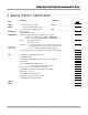
Advanced Instruments Inc. 2 Quality Control Certification Date: Customer: Order No.: Model: GPR-1900 ppm Oxygen Analyzer Sensor: ( ) GPR-12-333 ppm Oxygen Sensor ( ) XLT-12-333 ppm Oxygen Sensor Accessories: Owner’s Manual CABL-1008 Power Cord Configuration: Ranges: 0-10 ppm, 0-100 ppm, 0-1000 ppm, 0-1%, 0-25% A-1161-1 PCB Assembly Micro / Display – Software V.
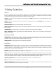
Advanced Instruments Inc. 3 Safety Guidelines General This section summarizes the essential precautions applicable to the GPR-1900 ppm Oxygen Analyzer. Additional precautions specific to individual analyzer are contained in the following sections of this manual. To operate the analyzer safely and obtain maximum performance follow the basic guidelines outlined in this Owner’s Manual.
Advanced Instruments Inc. Handling: Do not use force when using the switches and knobs. Before moving your analyzer be sure to disconnect the wiring/power cord and any cables connected to the output terminals located on the analyzer. Maintenance Serviceability: Except for replacing the oxygen sensor, there are no parts inside the analyzer for the operator to service. Only trained personnel with the authorization of their supervisor should conduct maintenance. Oxygen Sensor: DO NOT open the sensor.
Advanced Instruments Inc. 5 Operations Principle of Operation The GPR-1900 ppm Oxygen Analyzer incorporates several advanced galvanic fuel cell type sensors for parts-per-million ppm oxygen analysis. This model is configured for panel mounting and requires a 6”W x 3”H cutout with 4 holes for the studs located on the back side of the analyzer’s front panel. Optional mounting configurations include a 19” rack or wall mount enclosure with or without a sample system.
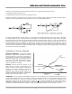
Advanced Instruments Inc. However, for optimal performance after exposing the sensor to air or elevated oxygen levels in terms of: 1) bringing the analyzer back online, and, 2) maximizing the service life of the sensor by isolating the sensor Advanced Instruments recommends the user employ one of the following ‘bypass sample system’ designs illustrated below. Preference is given to the illustration on the left because it is the surest and simplest approach.
Advanced Instruments Inc.
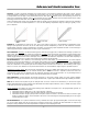
Advanced Instruments Inc. Note 4: Calibrating with a span gas approximating 10% of the full scale range near the expected oxygen concentration of the sample gas is acceptable but less accurate than ‘optimum calibration accuracy’ method recommended – the method usually depends on the gas available. Calibrating at the same 10% of the full scale range for measurements at the higher end of the range results in magnification of errors as discussed in Graph A and Example 1 and is not recommended.
Advanced Instruments Inc. Installation Considerations Gas Sample Stream: Ensure the gas stream composition of the application is consistent with the specifications and review the application conditions before initiating the installation. Consult the factory if necessary to ensure the sample is suitable for analysis. Note: In natural gas applications such as extraction and transmission, a low voltage current is applied to the pipeline itself to inhibit corrosion.
Advanced Instruments Inc. intended to measure elevated oxygen levels ranging from 50-100% oxygen) on the CAL or 0-25% range meets the 80% criteria discussed above.
Advanced Instruments Inc. Recommendations to avoid erroneous oxygen readings and damaging the sensor: ¾ Do not place your finger over the vent (it pressurizes the sensor) to test the flow indicator when gas is flowing to the sensor. Removing your finger (the restriction) generates a vacuum on the sensor and may damage the sensor (voiding the sensor warranty).
Advanced Instruments Inc. Gas Connections The GPR-1900 with its standard flow through configuration is designed for positive pressure samples and requires connections for incoming sample and outgoing vent lines. The user is responsible for calibration gases and the required components, see below. Flow rates of 1-5 SCFH cause no appreciable change in the oxygen reading.
Advanced Instruments Inc. 4. 5. 6. 7. To connect to an active relay or “fail safe”, connect the live cable to the common terminal C and the secondary cable to the normally open NO terminal. To break the connection upon relay activation, connect the secondary cable to the normally closed NC terminal. Insert the stripped end of the cables into the appropriate terminal slots assuring no bare wire remains exposed that could come in contact with the back panel of the analyzer enclosure.
Advanced Instruments Inc. Installing the Oxygen Sensor The GPR-1900 Oxygen Analyzer is equipped with an external oxygen sensor. They have been tested and calibrated by the manufacturer prior to shipment and are fully operational from the shipping containers. The sensor has not been installed at the factory and it will be necessary to install the sensor in the field. Caution: Review procedure before proceeding, mainly 2 and 9. Caution: DO NOT open the oxygen sensor.
Advanced Instruments Inc. Procedure: 1. With the span gas cylinder valve closed, install the regulator on the cylinder. 2. Open the regulator’s exit valve and partially open the pressure regulator’s control knob. 3. Open slightly the cylinder valve. 4. Loosen the nut connecting the regulator to the cylinder and bleed the pressure regulator. 5. Retighten the nut connecting the regulator to the cylinder 6. Adjust the regulator exit valve and slowly bleed the pressure regulator. 7.
Advanced Instruments Inc. MAIN MENU AUTO SAMPLE MANUAL SAMPLE CALIBRATION CONFIG ALARMS BYPASS ALARMS Range Selection The GPR-1900 analyzer is equipped with four (4) standard measuring ranges (see specification) and provides users with a choice of sampling modes. By accessing the MAIN MENU, users may select either the AUTO SAMPLING (ranging) or MANUAL SAMPLING (to lock on a single range) mode. Note: For calibration purposes, use of the AUTO SAMPLE mode is recommended.
Advanced Instruments Inc. MAIN MENU AUTO SAMPLE MANUAL SAMPLE CALIBRATION CONFIG ALARMS BYPASS ALARMS 5. 6. 7. MANUAL RANGE >>> 25% 1% 1000 ppm 100 ppm Advance the reverse shade cursor using the ARROW keys to highlight the desired MANUAL RANGE. Press the ENTER key to select the highlighted menu option. The following displays appears with the range selected and oxygen concentration of the sample gas: MANUAL RANGE 25% 1% 1000 ppm 100 ppm >>> 3.3 PPM AUTO SAMPLING 100 PPM RANGE 24.
Advanced Instruments Inc. MAIN MENU AUTO SAMPLE MANUAL SAMPLE CALIBRATION CONFIG ALARMS BYPASS ALARMS 5. 6. 7. MAIN MENU SET ALARM 1 SET ALARM 2 SET ALARM DELAY ALARM 1 HI/LO ALARM 2 HI/LO ALARMS AUDIBLE/SILENT >>> Advance the reverse shade cursor using the ARROW keys to highlight the SET ALARM 1 option. Press the ENTER key to select the highlighted menu option.
Advanced Instruments Inc. 3.3 PPM AUTO SAMPLING 100 PPM RANGE 24.5 C LO1 2 PPM 10 PPM HI2 Repeat the steps above to set the ALARM 2 value: MAIN MENU AUTO SAMPLE MANUAL SAMPLE CALIBRATION CONFIG ALARMS BYPASS ALARMS MAIN MENU SET ALARM 1 SET ALARM 2 SET ALARM DELAY ALARM 1 HI/LO ALARM 2 HI/LO ALARMS AUDIBLE/SILENT >>> Set Alarm Delay: Once the values for ALARM 1 and ALARM 2 have been entered, the user may elect to delay the activation of the local alarms and relay contacts for up to 99 minutes.
Advanced Instruments Inc. 12. The system returns the SAMPLING mode and displays: 3.3 PPM AUTO SAMPLING 100 PPM RANGE 24.5 C LO1 2 PPM 10 PPM HI2 Set HI/LO Alarms: 1. Access the MAIN MENU by pressing the MENU key. 2. Advance the reverse shade cursor using the ARROW keys to highlight CONFIG ALARMS. 3. Press the ENTER key to select the highlighted menu option. 4. The following displays appears: MAIN MENU MAIN MENU AUTO SAMPLE MANUAL SAMPLE CALIBRATION CONFIG ALARMS BYPASS ALARMS 5. 6.
Advanced Instruments Inc. 5. 6. Advance the reverse shade cursor using the ARROW keys to highlight the ALARMS AUDIBLE/SILENT option, which appear as either ALARMS AUDIBLE or ALARMS SILENT. Press the ENTER key to toggle and change the displayed setting. After 3 seconds, the system returns to SAMPLING mode. 3.3 PPM AUTO SAMPLING 100 PPM RANGE 24.
Advanced Instruments Inc. Zero Calibration In theory, the oxygen sensor produces no signal output when exposed to an oxygen free sample gas.
Advanced Instruments Inc. 0.000 PPM ZERO CALIBRTION ENTER TO CALIBRATE MENU TO ABORT 8. 9. Press the ENTER key to calibrate or MENU key to abort and return to SAMPLING mode. Allow approximately 60 seconds for the calibration process while the processor determines whether the signal output or reading has stabilized within 50% of the full scale low range. 10.
Advanced Instruments Inc. Output Zero: In rare instances the 4-20mA signal output may not agree to the reading displayed by the LCD. This feature enables the user to adjust the 4mA signal output when the LCD displays 00.00. Compute the adjustment value as described in Appendix B or consult the factory. Note: Adjust the 20mA signal output with the OUTPUT SPAN option described below. The true adjustment value must be determined empirically by trial and error.
Advanced Instruments Inc. Span Calibration Maximum drift from calibration temperature is approximately 0.11% of reading per °C. The analyzer has been calibrated at the factory. However, in order to obtain reliable data, the analyzer must be calibrated at the initial start-up and periodically thereafter. The maximum calibration interval recommended is approximately 3 months, or as determined by the user’s application.
Advanced Instruments Inc. MAIN MENU AUTO SAMPLE MANUAL SAMPLE CALIBRATION CONFIG ALARMS BYPASS ALARMS 5. 6. 7. 8. 9. 3.3 AUTO SAMPLING 100 PPM RANGE 24.5 C LO1 2 PPM AUTO SAMPLE MANUAL SAMPLE CALIBRATION CONFIG ALARMS BYPASS ALARMS 15. 16. 17. 18. 10 PPM HI2 Return to the MAIN MENU by pressing the MENU key. Advance the reverse shade cursor using the ARROW keys to highlight CALIBRATION. Press the ENTER key to select the highlighted menu option.
Advanced Instruments Inc. 22. Repeat steps 20 and 21 until the complete SPAN value has been entered. 23. Save the adjustment value by pressing the ENTER key or abort by pressing the MENU key. 24. Allow approximately 60 seconds for the calibration process while the processor determines whether the signal output or reading has stabilized within 60% of the full scale low range.
Advanced Instruments Inc. Output Span: In rare instances the 4-20mA signal output may not agree to the reading displayed by the LCD. This feature enables the user to adjust the 20mA signal output should the LCD display not agree. Note: Adjust the 4mA signal output with the OUTPUT ZERO option described above. Procedure: 1. Access the MAIN MENU by pressing the MENU key. 2. Advance the reverse shade cursor using the ARROW keys to highlight CALIBRATION. 3.
Advanced Instruments Inc. Sampling GPR-1900 Oxygen Analyzer requires positive pressure to flow the sample gas by the sensor to measure the oxygen concentration in a sample gas. See Sample System and Pressure & Flow at the beginning of Section 5 Operations.
Advanced Instruments Inc. 6 Maintenance There are no moving parts in the analyzer given the modular nature of the electronics and sensor. Cleaning the electrical contacts when replacing the sensor is the extent of the maintenance requirements of this analyzer. Serviceability: Except for replacing the oxygen sensor, there are no parts inside the analyzer for the operator to service. Only trained personnel with the authorization of their supervisor should conduct maintenance.
Advanced Instruments Inc.
Advanced Instruments Inc. Symptom Possible Cause Recommended Action Erratic O2 reading or No O2 reading Change in sample pressure Sensors without PCB use mV setting.
Advanced Instruments Inc.
Advanced Instruments Inc.
Advanced Instruments Inc. 9 Warranty The design and manufacture of GPR Series oxygen analyzers, monitors and oxygen sensors are performed under a certified Quality Assurance System that conforms to established standards and incorporates state of the art materials and components for superior performance and minimal cost of ownership.
Advanced Instruments Inc. 10 MSDS Material Safety Data Sheet Product Identification Product Name Oxygen Sensor Series - PSR, GPR, AII, XLT Synonyms Electrochemical Sensor, Galvanic Fuel Cell Manufacturer Analytical Industries Inc., 2855 Metropolitan Place, Pomona, CA 91767 USA Emergency Phone Number 909-392-6900 Preparation / Revision Date January 1, 1995 Notes Oxygen sensors are sealed, contain protective coverings and in normal conditions do not present a health hazard.
Advanced Instruments Inc. Spill or Leak Steps if material is released Sensor is packaged in a sealed plastic bag, check the sensor inside for electrolyte leakage. If the sensor leaks inside the plastic bag or inside an analyzer sensor housing do not remove it without rubber or latex gloves and safety glasses and a source of water. Flush or wipe all surfaces repeatedly with water or wet paper towel (fresh each time). Disposal In accordance with federal, state and local regulations.
Advanced Instruments Inc. Appendix B Correlating Readings - LCD Display and 4-20mA Output In rare instances the 4-20mA signal output may not agree to the reading displayed by the LCD. The Output Zero and Output Span features enable the user to adjust the 4mA signal output to correlate with the reading displayed by the LCD. For optimum accuracy make two separate adjustments as follows: 1. OUTPUT ZERO feature: To adjust the 4mA signal output and requires zero gas. 2.
Advanced Instruments Inc. 100.0 OUTPUT ZERO OFFSET PRESS UP OR DOWN TO CHANGE VALUE ENTER TO SAVE MENU TO RETURN 14. Enter the calculated adjustment value. Note: Once the initial adjustment is made and checked at the PLC it may be necessary to fine tune the initial adjustment by repeating. Any additional percent error must be added or subtracted from the initial adjustment value 000.0 OUTPUT ZERO OFFSET PRESS UP OR DOWN TO CHANGE VALUE ENTER TO SAVE MENU TO RETURN 15.
Advanced Instruments Inc. 27. Enter the calculated adjustment value, refer to example described above. Note: Once the initial adjustment is made and checked at the PLC it may be necessary to fine tune the initial adjustment by repeating. Any additional percent error must be added or subtracted from the initial adjustment value 064.0 OUTPUT SPAN OFFSET PRESS UP OR DOWN TO CHANGE VALUE ENTER TO SAVE MENU TO RETURN . 28.