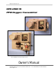
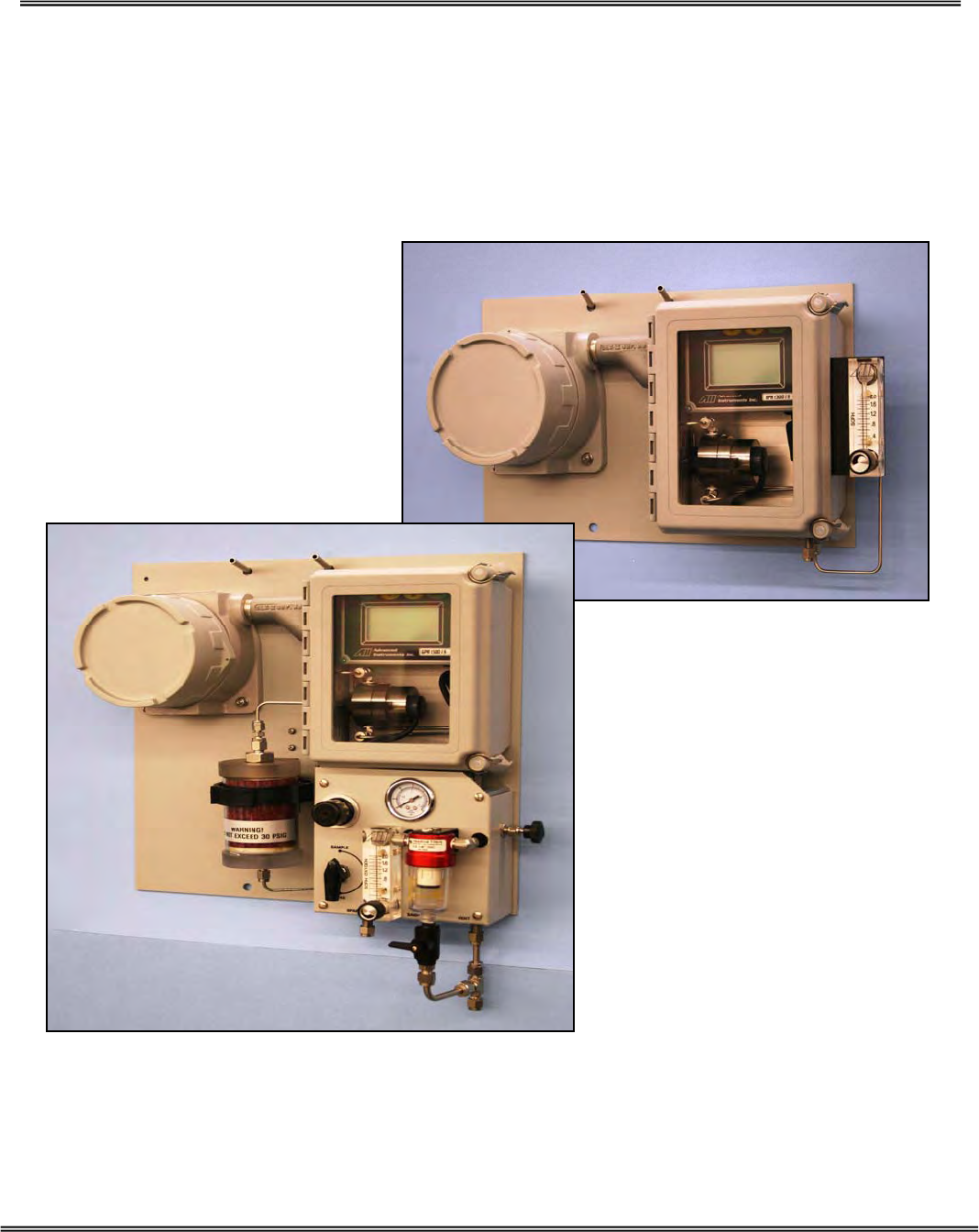
Advanced Instruments Inc. GPR-1800 IS PPM Oxygen Transmitter Shown with Optional A-3393-6 Sample System Owner’s Manual 2855 Metropolitan Place, Pomona, California 91767 USA ♦ Tel: 909-392-6900, Fax: 909-392-3665, email: info@aii1.
Advanced Instruments, Inc Table of Contents Introduction 1 Quality Control Certification 2 Safety 3 Features & Specifications 4 Operation 5 Maintenance 6 Spare Parts 7 Troubleshooting 8 Warranty 9 Material Safety Data Sheets 10 Drawings A/R Explosion Proofing Electrical Connections Appendix A Correlating readings – LCD display to 4-20mA signal output Appendix B H2S Scrubber, Sample System, Media MSDS Appendix F Maintenance H2S Scrubber & Coalescing Filter Appendix G The ap
Advanced Instruments, Inc 1. Introduction Your new oxygen transmitter incorporates an advanced electrochemical sensor specific to oxygen along with state-of-the-art digital electronics designed to give you years of reliable precise oxygen measurements in a variety of industrial oxygen applications. More importantly, it has been constructed as intrinsically safe in accordance with ATEX Directives 94/9/EC for use in hazardous areas in zone 1 Group C and D.
Advanced Instruments, Inc 3. General Safety & Installation This section summarizes the essential precautions applicable to the GPR-1500IS Oxygen Transmitter. Additional precautions specific to individual transmitter are contained in the following sections of this manual. To operate the transmitter safely and obtain maximum performance follow the basic guidelines outlined in this Owner’s Manual.
Advanced Instruments, Inc 2.
Advanced Instruments, Inc Maintenance Serviceability: Except for replacing the oxygen sensor, there are no parts inside the transmitter for the operator to service. Only trained personnel with the authorization of their supervisor should conduct maintenance. Oxygen Sensor: DO NOT open the sensor. The sensor contains a corrosive liquid electrolyte that could be harmful if touched or ingested, refer to the Material Safety Data Sheet contained in the Owner’s Manual appendix.
Advanced Instruments, Inc Expected Sensor Life: With reference to the publish specification located at the last page of this manual, the expected life of all oxygen sensors is predicated on oxygen concentration (< 1000 ppm for PPM sensor or air for % sensor), temperature (77°F/25°C) and pressure (1 atmosphere) in “normal” applications. Deviations from standard conditions will affect the life of the sensor. As a rule of thumb sensor life is inversely proportional to changes in the pressure and temperature.
Advanced Instruments, Inc Outlet Pressure: In applications where sample pressure is positive, the sample must be vented to an exhaust pipe at a pressure less than the inlet pressure so that the sample gas can flow through the sensor housing. Ideally, the sample must be vented to atmospheric pressure. Note: The sensor may be used at a slight positive pressure (e.g., when sample is vented to a common exhaust where the pressure might be higher than 1 atmosphere).
Advanced Instruments, Inc by purging with zero or a gas with a low PPM oxygen concentration is recommended after the cleaning process is completed. Mounting: The analyzer is approved for indoor as well as outdoor use. However, avoid mounting in an area where direct sun might heat up the analyzer beyond the recommended operating temperature range. If possible, install a small hood over the analyzer for rain water drain and to prevent over-heating of analyzer.
Advanced Instruments, Inc 4.
Advanced Instruments, Inc 5. Operation Principle of Operation The GPR-1800 IS Oxygen Transmitter incorporates advanced galvanic fuel cell type oxygen sensors. These sensors are very specific to oxygen and generate an electrical signal proportional to the amount of oxygen present in a gas stream. The selection of a particular type of sensor depends on the composition of the sample gas stream. Consult the factory for recommendation. The transmitter is configured in two sections.
Advanced Instruments, Inc Advanced Galvanic Sensor Technology All galvanic type sensors function on the same principle and are specific to oxygen.
Advanced Instruments, Inc Sample System The standard GPR-1800 IS is supplied without a sample conditioning system thereby giving users the option of adding their own or purchasing a factory designed sample conditioning system, see section 2 QC Certification for optional equipment ordered. Whatever the choice, the sample must be properly conditioned before introducing it to the sensor to ensure an accurate measurement.
Advanced Instruments, Inc Example 1: As illustrated by Graph A, any error during a span adjustment at lower end of the scale, e.g., 20.9% (air) on a 100% full scale range, would be multiplied by a factor of 4.78 (100/20.9) when making measurements close to 100% O2. Conversely, an error during a span adjustment close to the top end of the range, e.g., at 100% is reduced proportionately for measurements of oxygen concentrations near the bottom end of the range.
Advanced Instruments, Inc Mounting the Transmitter The GPR-1800 IS analyzer consists of two interconnected enclosures (without the optional sample conditioning system and panel) and measures 8”H x 15-3/4”W x 7”D. This configuration is designed to be mounted directly to any flat vertical surface, wall or bulkhead plate by using eight (4) of the appropriate screws.
Advanced Instruments, Inc Gas Connections The GPR-1800 IS with its standard flow through configuration is designed for positive pressure samples and requires connections for incoming sample and outgoing vent lines. Zero and span inlet ports are offered as part of the optional sample systems. The user is responsible for calibration gases and other required components, see below. Procedure: Caution: Do not change the factory setting until instructed to do in this manual.
Advanced Instruments, Inc Electrical Connections Incoming power and signal output connections are made to a terminal block mounted on a PCB located in the explosion proof enclosure. Do not supply voltage more than specified in this manual and noted near the power input terminal of the analyzer. The PCB in the explosion proof enclosure contains a power limiting intrinsic safety barrier that limit the total power available at the PCB electronics mounted in the general purpose enclosure.
Advanced Instruments, Inc Hazardous Area Installation: The GPR-1800 IS may be installed in a hazardous area with proper insulation of the incoming power, see Appendix A. A 12-24 VDC power supply with two (2) conductor shielded cable is recommended. The power cable to the Ex enclosure must be supplied through a conduit approved for use in hazardous area. Secure the two wires to the power input terminal block by using the two integral screws of the terminal block. Do not substitute terminal screws.
Advanced Instruments, Inc Installing the Oxygen Sensor The GPR-1800IS Oxygen Transmitter is equipped with a SS sensor housing. This housing offers ease of replacement of sensor and at the same time prevents any air leakage into the system. The two sections of the sensor are held together by a metal clamp secured in place by easily accessed bolt. The integrity of the sensor housing has been tested at the factory prior to shipment and is fully operational from the shipping container.
Advanced Instruments, Inc Span Gas Preparation Note: The GPR-1800 IS can be calibrated by using ambient air. However, it can also be calibrated by using a certified span gas. Air calibration can be achieved right after installing the sensor in the housing. Subsequent calibration, where the sensor has been exposed to a sample gas, air calibration can be achieved by either removing the sensor from the sensor housing or by pushing the air through the sensor housing.
Advanced Instruments, Inc Establishing Power to Electronics Once the two power input wires of the shielded cable are properly connected to the terminals inside the Ex enclosure as described above, connect the other end of the two wires to a suitable 12-24 VDC power supply such as a battery, PLC, DCS, etc. The digital display responds instantaneously.
Advanced Instruments, Inc Main Menu To access the MAIN MENU, press the MENU (ESC) key and the following screen will appear. MAIN MENU AUTO SAMPLE MANUAL SAMPLE CALIBRATION CONFIG ALARMS BYPASS ALARMS This screen shows various options available. You can use the UP and DOWN arrow key to move the cursor and highlight the desired function. After moving the cursor to the desired function, press ENTER to access that function.
Advanced Instruments, Inc For example, if the transmitter is reading 1% on the 0-10% range and an upset occurs, the display will shift to the 0-25% range when the oxygen reading exceeds 9.9%. Conversely, once the upset condition is corrected, the display will shift back to the 0-10% range when the oxygen reading drops to 8.5%. Manual Sampling Access the MAIN MENU by pressing the MENU key. Advance the reverse shade cursor using the ARROW keys to highlight MANUAL SAMPLE.
Advanced Instruments, Inc NOTE: With oxygen reading above 110% of the selected range, the mA signal output will increase but will freeze at a maximum value of 24 mA. After the oxygen reading falls below the full scale range, the mA signal will become normal. Calibration of Transmitter The electrochemical oxygen sensors generate an electrical current that is linear or proportional to the oxygen concentration in a sample gas. In the absence of oxygen the sensor exhibits an absolute zero, i.e.
Advanced Instruments, Inc exposure to high O2 concentrations or air is significantly different if a sensor is being installed than if the sensor had been in-service at low oxygen levels for more than 1 week. Sensor PPM Fuel Cell Calibration at Install Air to .1% < 1 min Air to 100 PPM < 5 min Air to < 10PPM < 60 min In-service Calibration Similar Less than 45 min The above times assume the introduction of a zero gas (low level of oxygen in nitrogen) after span calibration.
Advanced Instruments, Inc Span Gas vs. Air Calibration The analyzer can be calibrated by using ambient air (20.9% O2 ) or a certified span gas. The only advantage of using a certified span gas for calibration is the fast recovery time to low PPM level after calibration. For example, if the analyzer is calibrated by using 8 PPM span gas, the analyzer will recover to within 0.1 PPM of the original reading within five minutes.
Advanced Instruments, Inc CALIBRATION will appear and the analyzer will return to Sample mode without completing the Zero calibration. Both the Zero Calibrate and Span Calibrate functions result in the following displays: PASSED CALIBRATION OR FAILED CALIBRATION Default Zero The feature will eliminate any previous zero calibration adjustment and display the actual signal output of the sensor at a specified oxygen concentration. For example, assuming a zero gas is introduced, the display above 0.
Advanced Instruments, Inc Analog Output with Zero O2 In rare instances the 4-20mA signal output may not agree to the reading displayed on the LCD. This feature enables the user to adjust the 4mA signal output when the LCD displays 00.00. Note Adjust the 20mA signal output with the OUTPUT SPAN option described below. Access the MAIN MENU by pressing the MENU key. Advance the reverse shade cursor using the ARROW keys to highlight CALIBRATION.
Advanced Instruments, Inc Repeat the OUTPUT ZERO OFFSET routine until the output is 4 mA . Save the adjustment value by pressing the ENTER key or abort by pressing the MENU key. After adjustment, the system returns to the SAMPLING mode.
Advanced Instruments, Inc GAS CONCENTRATION PERCENT PPM The following displays appear: 000.00 % PRESS UP OR DOWN TO CHANGE VALUE ENTER TO SAVE MENU TO RETURN 0.55% >>> SPAN CLAIBRATION ENTER TO CALIBRATE MENU TO ABORT Press the ENTER key to advance the underline cursor right or press the MENU key to advance the underline cursor left to reach to the desired digit of the alarm value. Repeat until the complete span value has been entered. Press the ENTER key to accept SPAN CALIBRATION.
Advanced Instruments, Inc Disconnect the span gas line and replace it with the sample gas line. Default Span With factory default span, previous calibration data stored in the memory is removed and the sensitivity of the analyzer is reset to the value based on the average output of the oxygen sensor at a specific oxygen concentration.
Advanced Instruments, Inc MAIN MENU AUTO SAMPLE CALIBRATION >>> SPAN CALIBRATE MANUAL SAMPLE ZERO CALIBRATE CALIBRATION DEFAULT SPAN CONFIG ALARMS DEFAULT ZERO BYPASS ALARMS OUTPUT SPAN OUTPUT ZERO Advance the reverse shade cursor using the ARROW keys to highlight DEFAULT SPAN. Press the ENTER key to select the highlighted menu option. The following display appears 100.
Advanced Instruments, Inc For sample gases under positive pressure, the user must provide a means of controlling the inlet pressure between 5-30 psig and the flow of the sample gas between 1-5 SCFH, a flow rate of 1-2 SCHF is recommended For sample gases under atmospheric or slightly negative pressure, an optional sampling pump is recommended to push the sample the sensor housing. Generally, when using a pump, no pressure regulation or flow control device is involved.
Advanced Instruments, Inc 6. Maintenance Generally, cleaning the electrical contacts inside of the upper section of the sensor housing or replacing filter element of the coalescing filter is the extent of the maintenance requirements of this transmitter. Serviceability: Except for replacing the oxygen sensor, there are no parts inside the transmitter for the operator to service. Only trained personnel with the authorization of their supervisor should conduct maintenance. 7.
Advanced Instruments, Inc 8.
Advanced Instruments, Inc Symptom Possible Cause Recommended Action Response time slow Air leak, dead legs, distance of sample line, low flow rate, volume of optional filters and scrubbers Leak test (above), reduce dead volume or increase flow rate O2 reading doesn’t agree to expected O2 values Pressure and temperature of the sample is different than span gas Abnormality in gas Calibrate the transmitter (calibrate at pressure and temperature of sample) Qualify the gas (use a portable analyzer as a
Advanced Instruments, Inc or No O2 reading accompanied by electrolyte leakage suddenly removing the restriction draws a vacuum on the sensor or partially opened valves upstream of the transmitter when using a pump downstream of the transmitter to draw sample from a process at atmospheric pressure or under a slight vacuum. Placing a vacuum on the sensor in excess 10” of water column is strongly discouraged.
Advanced Instruments, Inc 9. Warranty The design and manufacture of GPR Series oxygen transmitters/analyzers, monitors and oxygen sensors are performed under a certified Quality Assurance System that conforms to established standards and incorporates state of the art materials and components for superior performance and minimal cost of ownership.
Advanced Instruments, Inc Be sure to pack the analyzer securely. Include your name, address, telephone number, and a description of the operating problem. After repairing or, at our option, replacing your Advanced Instruments Inc. analyzer, we will ship it to you at no cost for parts and labor. 10. MSDS – Material Safety Data Sheet Product Identification Product Name Oxygen Sensor Series - PSR, GPR, AII, XLT Synonyms Electrochemical Sensor, Galvanic Fuel Cell Manufacturer Advanced Instruments Inc.
Advanced Instruments, Inc Flammable Limits Not flammable Extinguishing Method Not applicable Special Fire Fighting Procedures Not applicable Unusual Fire and Explosion Hazards Not applicable Reactivity Data Stability Stable Conditions Contributing to Instability None Incompatibility KOH = Avoid contact with strong acids or Acetic Acid = Avoid contact with strong bases Hazardous Decomposition Products KOH = None or Acetic Acid = Emits toxic fumes when heated Conditions to Avoid KOH = None o
Advanced Instruments, Inc Special Precautions Precautions Transportation 41 Do not remove the sensor’s protective Teflon and PCB coverings. Do not probe the sensor with sharp objects. Wash hands thoroughly after handling. Avoid contact with eyes, skin and clothing. Empty sensor body may contain hazardous residue.
Advanced Instruments, Inc Appendix A Electrical connections require an approved explosion proof sealing fitting and packing around wires and cables (for incoming power for the analyzer electronics and 4-20mA signal output) coming into and out of the explosion proof enclosure that houses the power supply/signal output PCB. Full compliance with hazardous area electrical code requires the user to supply glands, fittings and/or conduit commensurate with the level of protection or classification desired.
Advanced Instruments, Inc Caution: At least five threads must engage on all fill plugs. Caution: Prolonged breathing or ingestion may cause internal obstruction, seek medical care. Do not get into eyes or on skin – if cement touches eyes or skin, flush with water for 15 minutes. Large amounts on skin when hardening may cause skin burn. Use adequate ventilation.
Advanced Instruments, Inc Appendix B Matching - LCD Display with 4-20mA Output In rare instances the 4-20mA signal output may not agree with the reading displayed on the LCD. The Output Zero and Output Span features enable the user to adjust the 4mA and 20 mA signal output matching with the reading displayed by the LCD. For optimum accuracy make two separate adjustments as follows: 1. OUTPUT ZERO feature: To adjust the 4mA signal output and requires zero gas. 2.
Advanced Instruments, Inc Adjust 4 mA with Zero O2 Access the MAIN MENU by pressing the MENU key. Advance the reverse shade cursor using the ARROW keys to highlight CALIBRATION. Press the ENTER key to select the highlighted menu option. The following displays appear: MAIN MENU AUTO SAMPLE CALIBRATION >>> SPAN CALIBRATE MANUAL SAMPLE ZERO CALIBRATE CALIBRATION DEFAULT SPAN DEFAULT ZERO OUTPUT SPAN OUTPUT ZERO Advance the reverse shade cursor using the ARROW keys to highlight DEFAULT ZERO.
Advanced Instruments, Inc Adjust 20 mA at known O2 Access the MAIN MENU by pressing the MENU key. Advance the reverse shade cursor using the ARROW keys to highlight CALIBRATION. Press the ENTER key to select the highlighted menu option. The following displays appear: MAIN MENU AUTO SAMPLE CALIBRATION >>> SPAN CALIBRATE MANUAL SAMPLE ZERO CALIBRATE CALIBRATION DEFAULT SPAN DEFAULT ZERO OUTPUT SPAN OUTPUT ZERO Advance the reverse shade cursor using the ARROW keys to highlight OUTPUT SPAN.
Advanced Instruments, Inc 47
Advanced Instruments, Inc 48
Advanced Instruments, Inc 49
Advanced Instruments, Inc Appendix G Maintenance – H2S Scrubber Servicing any of the H2S scrubbers will depend on several factors as illustrated in Appendix F and include: the (average) H2S concentration, volume of scrubber media and flow rate through the scrubber (often times maximizing the service life means longer system response time) see Appendix F. Required equipment: 1. 2x 7/16” open end wrenches 2. 1x 9/16” open end wrench 3.
Advanced Instruments, Inc The bowl seals to the head section with an o-ring, do not lose the o-ring. The filter element screws into the head section, carefully turn it counter clockwise and remove it from the head. Using the damp cloth, clean the inside of the bowl and the o-ring before reassembling – apply a very thin coat of lubricant to the o-ring. Reverse the above steps to re-assemble the filter.