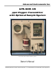
Advanced Instruments Inc. GPR-1800 AIS ppm Oxygen Transmitter with Optional Sample System (shown with optional sample conditioning system) Owner’s Manual 2855 Metropolitan Place, Pomona, California 91767 USA ♦ Tel: 909-392-6900, Fax: 909-392-3665, e-mail: info@aii1.
Advanced Instruments Inc.
Advanced Instruments Inc. 2 Quality Control Certification Date: Customer: Order No.
Advanced Instruments Inc. 3 Safety General This section summarizes the essential precautions applicable to the GPR-1800AIS ppm Oxygen Transmitter. Additional precautions specific to individual transmitter are contained in the following sections of this manual. To operate the transmitter safely and obtain maximum performance follow the basic guidelines outlined in this Owner’s Manual.
Advanced Instruments Inc. Operating Temperature: The maximum operating temperature is 45º C on an intermittent basis unless the user is willing to accept a dramatic reduction in expected sensor life – refer to analyzer specification where expected sensor life is specified at less than 1000 ppm oxygen at 25°C and 1 atmosphere of pressure. Heat: Situate and store the transmitter away from sources of heat. Liquid and Object Entry: The transmitter should not be immersed in any liquid.
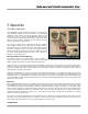
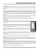
Advanced Instruments Inc. 5 Operation Principle of Operation The GPR-1800AIS oxygen transmitter incorporates a variety of ppm range advanced galvanic fuel cell type sensors. The transmitter is configured in two sections. The signal processing electronics and sensor are housed in a general purpose NEMA 4X rated enclosure. The terminals for incoming power, power supply, signal output, alarm relay contacts and intrinsic safety barriers are mounted on a PCB housed in an explosion proof enclosure.
Advanced Instruments Inc. The GPR-1800AIS is supplied without a sample conditioning system thereby giving users the option of adding their own or purchasing a factory designed sample conditioning system. Whatever the choice, the sample must be properly presented to the sensor to ensure an accurate measurement. Users interested in adding their own sample conditioning system should consult the factory. Advanced Instruments Inc.
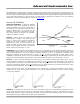
Advanced Instruments Inc. Zero Calibration: In theory, the electrochemical galvanic fuel cell type oxygen has an absolute zero meaning it produces no signal output when exposed to an oxygen free sample gas. In reality, expect the analyzer to generate an oxygen reading when sampling oxygen free sample gas due to contamination or quality of the zero gas; minor leakage in the sample line connections; residual oxygen dissolved in the sensor’s electrolyte; and, tolerances of the electronic components.
Advanced Instruments Inc. Installation Considerations Gas Sample Stream: Ensure the gas stream composition of the application is consistent with the specifications and review the application conditions before initiating the installation. Consult the factory if necessary to ensure the sample is suitable for analysis. Note: In natural gas applications such as extraction and transmission, a low voltage current is applied to the pipeline itself to inhibit corrosion.
Advanced Instruments Inc. Recommendation: Based on the inherent linearity of the galvanic oxygen sensor enables the user to calibrate the analyzer with ambient air (20.9% oxygen) and operate the analyzer within the stated accuracy spec on the lowest most sensitive range available with the analyzer – there is no need to recalibrate the analyzer with span gas containing a lower oxygen concentration.
Advanced Instruments Inc. Application Pressure - Atmospheric or Slightly Negative: For accurate ppm range oxygen measurements, an optional external sampling pump should be positioned downstream of the sensor to draw the sample from the process, by the sensor and out to atmosphere. A flow meter is generally not necessary to obtain the recommended flow rate with most sampling pumps.
Advanced Instruments Inc. These unpainted areas are protected by gaskets and contribute to maintaining the NEMA 4 rating. Do not paint these areas. Painting will negate the RFI protection. Note: If equipped with the optional H2S sample conditioning system, the transmitter and sample system are mounted to a back panel which has four (4) holes for mounting the 15-3/4”H x 15-3/4”W x 7”D panel to any vertical flat surface.
Advanced Instruments Inc. 3. 4. 5. 6. 7. 8. Ensure the positive and negative terminals of the power supply are connected to the appropriate terminals of the barrier strip as marked. Connect the shielding of the cable to the ground screw inside the enclosure. Note: The terminals snap together, making it possible to detach the section with the ground, install the shielded cable and reinstall. Replace the cover.
Advanced Instruments Inc. Required components: 1. Certified span gas cylinder with an oxygen concentration, balance nitrogen, approximating 80% of the full scale range above the intended measuring range. 2. Regulator to reduce pressure to between 5 and 30 psig. 3. Flow meter to set the flow between 1-5 SCFH, 4. Suitable fittings and a 4-6 ft. in length of 1/8” dia. metal tubing to connect the regulator to the flow meter inlet 5. Suitable fitting and a 4-6 ft. in length of 1/8” dia.
Advanced Instruments Inc. 3. 4. yellow DOWN ARROW green MENU (escape) Main Menu Access the MAIN MENU by pressing the MENU key: MAIN MENU AUTO SAMPLE MANUAL SAMPLE CALIBRATION CONFIG ALARMS BYPASS ALARMS Range Selection The GPR-1800AIS transmitter is equipped with five (5) standard measuring ranges (see specification) and provides users with a choice of sampling modes. By accessing the MAIN MENU, users may select either the AUTO SAMPLING (ranging) or MANUAL SAMPLING (to lock on a single range) mode.
Advanced Instruments Inc. 2. 3. 4. Advance the reverse shade cursor using the ARROW keys to highlight MANUAL SAMPLE. Press the ENTER key to select the highlighted menu option. The following display appears: MAIN MENU MANUAL RANGE >>> AUTO SAMPLE MANUAL SAMPLE CALIBRATION CONFIG ALARMS BYPASS ALARMS 5. 6. 7. 25% 1% 1000 PPM 100 PPM 10 PPM Advance the reverse shade cursor using the ARROW keys to highlight the desired MANUAL RANGE. Press the ENTER key to select the highlighted menu option.
Advanced Instruments Inc. Alarms The CONFIG ALARMS features a system that can be configured in the field.
Advanced Instruments Inc. 9. Press the ENTER key to select the highlighted menu option. Note: The PERCENT (of FS) alarm value is entered with one decimal, the PPM (oxygen) alarm value is entered as an integer. 01.0 GAS CONCENTRATION >>> PERCENT PPM SET ALARM 1 VALUE PRESS UP OR DOWN TO CHANGE VALUE ENTER TO SAVE MENU TO RETURN 002 GAS CONCENTRATION >>> PERCENT PPM SET ALARM 1 VALUE PRESS UP OR DOWN TO CHANGE VALUE ENTER TO SAVE MENU TO RETURN 10.
Advanced Instruments Inc. Once the values for ALARM 1 and ALARM 2 have been entered, the user may elect to delay the activation of the local alarms and relay contacts for up to 99 minutes. This feature allows users to distinguish between transient occurrences and true upset conditions. This feature can be particularly useful on remote applications without affecting the 4-20mA signal output. 1. Access the MAIN MENU by pressing the MENU key. 2.
Advanced Instruments Inc. 3. 4. Press the ENTER key to select the highlighted menu option. The following displays appears: MAIN MENU MAIN MENU >>> AUTO SAMPLE MANUAL SAMPLE CALIBRATION CONFIG ALARMS BYPASS ALARMS 5. 6. SET ALARM 1 SET ALARM 2 SET ALARM DELAY ALARM 1 HI/LO ALARM 2 HI/LO ALARMS AUDIBLE/SILENT Advance the reverse shade cursor using the ARROW keys to highlight the ALARM 1 option, which appears as either ALARM 1 HI or ALARM 1 LO.
Advanced Instruments Inc. 3.3 PPM AUTO SAMPLING 10 PPM RANGE 24.5 C 100 KPA LO1 2PPM 10PPM HI2 Bypass Alarms: This feature, separate from CONFIG ALARMS above, enables the user to disable the local audible alarm and relay contacts during calibration or servicing. The alarms are enabled when the alarm condition is corrected. 1. Access the MAIN MENU by pressing the MENU key. 2. Advance the reverse shade cursor using the ARROW keys to highlight BYPASS ALARMS. 3.
Advanced Instruments Inc. Zero Calibration In theory, the oxygen sensor produces no signal output when exposed to an oxygen free sample gas.
Advanced Instruments Inc. 6. 7. Press the ENTER key to select the highlighted menu option. The following displays appear: 0.000 PPM ZERO CALIBRTION ENTER TO CALIBRATE MENU TO ABORT 8. 9. Press the ENTER key to calibrate or MENU key to abort and return to SAMPLING mode. Allow approximately 60 seconds for the calibration process while the processor determines whether the signal output or reading has stabilized within 60% of the full scale low range. 10.
Advanced Instruments Inc. 7. The following display appears and after 3 seconds the system returns to the SAMPLING mode: 3.3 FACTORY DEFAULTS SET PPM AUTO SAMPLING 10 PPM RANGE 24.5 C LO1 2PPM 100 KPA 10PPM HI2 Output Zero In rare instances the 4-20mA signal output may not agree to the reading displayed by the LCD. This feature enables the user to adjust the 4mA signal output when the LCD displays 00.00. Note: Adjust the 20mA signal output with the OUTPUT SPAN. 1.
Advanced Instruments Inc. Span Calibration Maximum drift from calibration temperature is approximately 0.11% of reading per °C. The analyzer has been calibrated at the factory. However, in order to obtain reliable data, the analyzer must be calibrated at the initial start-up and periodically thereafter. The maximum calibration interval recommended is approximately 3 months, or as determined by the user’s application.
Advanced Instruments Inc. 3.3 MAIN MENU AUTO SAMPLE MANUAL SAMPLE CALIBRATION CONFIG ALARMS BYPASS ALARMS 8. 9. 10. 11. 12. 13. AUTO SAMPLING 10 PPM RANGE 24.5 C 100 KPA LO1 1PPM 10PPM HI2 Return to the MAIN MENU by pressing the MENU key. Advance the reverse shade cursor using the ARROW keys to highlight CALIBRATION. Press the ENTER key to select the highlighted menu option. Repeat to select DEFAULT SPAN. Repeat to select SPAN CALIBRATE.
Advanced Instruments Inc. 27. Save the adjustment value by pressing the ENTER key or abort by pressing the MENU key. 28. Allow approximately 60 seconds for the calibration process while the processor determines whether the signal output or reading has stabilized within 60% of the full scale low range. Both the Zero Calibrate and Span Calibrate functions result in the following displays: PASSED CALIBRATION OR FAILED CALIBRATION 29.
Advanced Instruments Inc. Output Span: In rare instances the 4-20mA signal output may not agree to the reading displayed by the LCD. This feature enables the user to adjust the 20mA signal output should the LCD display not agree. Note: Adjust the 4mA signal output with the OUTPUT ZERO option described above. 1. Access the MAIN MENU by pressing the MENU key. 2. Advance the reverse shade cursor using the ARROW keys to highlight CALIBRATION. 3. Press the ENTER key to select the highlighted menu option. 4.
Advanced Instruments Inc. Sampling GPR-1800AIS ppm Oxygen Transmitter requires positive pressure to flow the sample gas by the sensor to measure the oxygen concentration in a sample gas. If not available see Pressure & Flow section. Note: Prematurely initiating the ZERO CALIBRATION procedure can cause the analyzer to display a negative reading in both the ZERO and SAMPLE modes. Prematurely initiating the SPAN CALIBRATION procedure can cause erroneously high offsets and inaccurate readings. Procedure: 1.
Advanced Instruments Inc. 6 Maintenance Generally, cleaning the electrical contacts or replacing filter elements is the extent of the maintenance requirements of this transmitter. Sensor Replacement Periodically, the oxygen sensor will require replacement. The operating life is determined by a number of factors that are influenced by the user and therefore difficult to predict.
Advanced Instruments Inc. 7 Spare Parts Recommended spare parts for the GPR-1800AIS ppm Oxygen Transmitter: Item No. Description GPR-12-333 XLT-12-333 ppm Oxygen Sensor ppm Oxygen Sensor Other spare parts: Item No.
Advanced Instruments Inc.
Advanced Instruments Inc.
Advanced Instruments Inc.
Advanced Instruments Inc. 9 Warranty The design and manufacture of GPR Series oxygen analyzers, monitors and oxygen sensors are performed under a certified Quality Assurance System that conforms to established standards and incorporates state of the art materials and components for superior performance and minimal cost of ownership.
Advanced Instruments Inc. 10 MSDS – Material Safety Data Sheet Product Identification Product Name Oxygen Sensor Series - PSR, GPR, AII, XLT Synonyms Electrochemical Sensor, Galvanic Fuel Cell Manufacturer Advanced Instruments Inc., 2855 Metropolitan Place, Pomona, CA 91767 USA Emergency Phone Number 909-392-6900 Preparation / Revision Date January 1, 1995 Notes Oxygen sensors are sealed, contain protective coverings and in normal conditions do not present a health hazard.
Advanced Instruments Inc. Spill or Leak Steps if material is released Sensor is packaged in a sealed plastic bag, check the sensor inside for electrolyte leakage. If the sensor leaks inside the plastic bag or inside an analyzer sensor housing do not remove it without rubber or latex gloves and safety glasses and a source of water. Flush or wipe all surfaces repeatedly with water or wet paper towel (fresh each time). Disposal In accordance with federal, state and local regulations.
Advanced Instruments Inc. Appendix A Electrical connections require an approved explosion proof sealing fitting and packing around wires and cables (for incoming power for the analyzer electronics, power failure alarm relays, set point alarm relays and 4-20mA signal output) coming into and out of the explosion proof enclosure that houses the interconnection PCB. Further full compliance with hazardous area electrical code requires the wires and cables to be protected by conduit.
Advanced Instruments Inc. Appendix B Correlating Readings – LCD Display and 4-20mA or 0-1V Signal Outputs In rare instances the signal output may not agree to the reading displayed by the LCD. The OUTPUT ZERO and OUTPUT SPAN features enable the user to adjust the signal output to correlate with the LCD reading. For optimum accuracy make two separate adjustments as follows: 1. OUTPUT ZERO feature: To adjust the 4mA or 0V signal output and requires zero gas. 2.
Advanced Instruments Inc. Output Zero Procedure: 1. Access the MAIN MENU by pressing the MENU key. 2. Advance the reverse shade cursor using the ARROW keys to highlight CALIBRATION. 3. Press the ENTER key to select the highlighted menu option. 4. The following displays appear: 5. 6. 7.
Advanced Instruments Inc. 5. 6. 7. MAIN MENU CALIBRATION AUTO SAMPLE MANUAL SAMPLE CALIBRATION CONFIG ALARMS BYPASS ALARMS SPAN CALIBRATE ZERO CALIBRATE DEFAULT SPAN DEFAULT ZERO OUTPUT SPAN OUTPUT ZERO >>> Advance the reverse shade cursor using the ARROW keys to highlight OUTPUT SPAN. Press the ENTER key to select the highlighted menu option. The following display appears: 100.0 OUTPUT SPAN OFFSET PRESS UP OR DOWN TO CHANGE VALUE ENTER TO SAVE MENU TO RETURN 8. 9.
Advanced Instruments Inc.
Advanced Instruments Inc.
Advanced Instruments Inc.
Advanced Instruments Inc.
Advanced Instruments Inc. Appendix G Maintenance – H2S Scrubber Servicing any of the H2S scrubbers will depend on several factors as illustrated in Appendix F and include: the (average) H2S concentration (average), volume of scrubber media and flow rate through the scrubber (often times maximizing the service life means longer system response time) see Appendix F. Required equipment: 1. 2x 7/16” open end wrenches 2. 1x 9/16” open end wrench 3. 1x 1” open end or adjustable wrench Procedure: 1.