Advanced Instruments Inc. GPR-1600 Series ppm Oxygen Analyzer Owner’s Manual 2855 Metropolitan Place, Pomona, California 91767 USA ♦ Tel: 909-392-6900, Fax: 909-392-3665, e-mail: info@aii1.
Advanced Instruments Inc. Table of Contents Introduction 1 Quality Control Certification 2 Safety & Installation 3 Features & Specifications 4 Operation 5 Maintenance 6 Spare Parts 7 Troubleshooting 8 Warranty 9 Material Safety Data Sheets 10 1 Introduction Your new oxygen analyzer is a precision piece of equipment designed to give you years of use in variety of industrial oxygen applications.
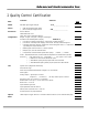
Advanced Instruments Inc. 2 Quality Control Certification Date: Customer: Order No.: Model: GPR-1600 ppm Oxygen Analyzer Sensor: ( ) GPR-12-333 ppm Oxygen Sensor ( ) XLT-12-333 ppm Oxygen Sensor S/N _____________________ S/N _____________________ Accessories: Owner’s Manual CABL-1008 Power Cord TOOL-1001 5/16” Combination Wrench Configuration: Ranges: 0-1 ppm, 0-10 ppm, 0-100 ppm, 0-1000 ppm A-1146-10 PCB Assembly Main / Display Software V.
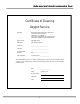
Advanced Instruments Inc. Certificate of Cleaning Oxygen Service Standard: Manufacturing Procedure No. P-1057 Rev-1, Compressed Gas Association, Publication: G-4.1 Edition 4, Title: Cleaning Equipment for Oxygen Service, Published 1/1/1996 and related publications Mfg. Item No.: GPR-1600 Series Description: ppm Oxygen Analyzer Serial No.
Advanced Instruments Inc. 3 Safety Guidelines Safety This section summarizes the basic precautions applicable to all analyzers. Additional precautions specific to individual analyzer are contained in the following sections of this manual. To operate the analyzer safely and obtain maximum performance follow the basic guidelines outlined in this Owner’s Manual. Caution: This symbol is used throughout the Owner’s Manual to Caution and alert the user to recommended safety and/or operating guidelines.
Advanced Instruments Inc. Installation Gas Sample Stream: Ensure the gas stream composition of the application is consistent with the specifications and review the application conditions before initiating the installation. Consult the factory to ensure the sample is suitable for analysis.
Advanced Instruments Inc.
Advanced Instruments Inc. Moisture & Particulates: Installation of a suitable coalescing or particulate filter is required to remove condensation, moisture and/or particulates from the sample gas to prevent erroneous analysis readings and damage to the sensor or optional components.
Advanced Instruments Inc.
Advanced Instruments Inc.
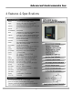
Advanced Instruments Inc. 5 Operation Principle of Operation The GPR-1600 ppm Oxygen Analyzers incorporates a a variety of ppm range advanced galvanic fuel cell type sensors and is configured for panel mounting and requires a 7.5x10.8” (T configuration) cutout with 4 holes for the analyzer’s front panel. Optional configurations include a panel mount (TO configuration) 7.75x7.75” with cutout; 19” bezel for rack mounting either the T or TO; 12x12x8” wall mount enclosure (GPR-1600W); 18.
Advanced Instruments Inc. Electronics The signal generated by the sensor is processed by state of the art low power micro-processor based digital circuitry. The first stage amplifies the signal. The second stage eliminates the low frequency noise. The third stage employs a high frequency filter and compensates for signal output variations caused by ambient temperature changes. The result is a very stable signal. Sample oxygen is analyzed very accurately.
Advanced Instruments Inc. Accuracy Overview Single Point Calibration: As previously described the galvanic oxygen sensor generates an electrical current proportional to the oxygen concentration in the sample gas. In the absence of oxygen the sensor exhibits an absolute zero, e.g. the sensor does not generate a current output in the absence of oxygen. Given these linearity and absolute zero properties, single point calibration is possible.
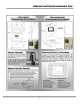
Advanced Instruments Inc. Mounting the Analyzer The standard GPR-1600 is designed to be panel mounted and requires a cutout that accommodates the enclosure and 4 mounting bolts. The design also lends itself to 19” rack mounting with an optional bezel or wall mount enclosures as illustrated below. Procedure: 1.
Advanced Instruments Inc.
Advanced Instruments Inc.
Advanced Instruments Inc. Gas Connections The GPR-1600 with its standard flow through configuration is designed for positive pressure samples and requires connections for incoming sample and outgoing vent lines, see illustrations above. The user is responsible for calibration gases and the components described below. Flow rates of 1-5 SCFH cause no appreciable change in the oxygen reading.
Advanced Instruments Inc. Electrical Connections: Incoming power for the 100-250V AC powered analyzers is supplied through a universal power entry module. A standard computer type power cord (P/N A-1008) is required for the universal power entry module. A well grounded insulated power cable is recommended to avoid noise resulting from unwanted interference.
Advanced Instruments Inc. Procedure: 1. As illustrated above the sensor, power and alarm relays and signal output connections are hard wired to screw type terminal blocks located at the rear of the analyzer. 2. Use a small bladed screwdriver to loosen the appropriate terminal screws as illustrated above. 3. Strip the wires of the cable no more than 3/16 inch. 4.
Advanced Instruments Inc. Alarms The analyzer is configured with two user adjustable threshold type alarm relays that can be configured in the field from the ALARM option on the MAIN MENU as follows: ¾ ¾ ¾ ¾ Establish independent set points Either Hi or Lo Either On or Off (enabled or disabled) Both temporarily defeated using a user entered ‘timeout’ period (normally minutes) The alarm set point represents a value.
Advanced Instruments Inc. Temperature Controlled Heater System with Runaway Protection Circuit The standard GPR-1600 Series analyzer is not equipped with the heater system. However, in anticipation of very low ppm (high ppb) oxygen analysis, the user may elect to add the heater system. If the analyzer is equipped with an optional temperature controlled heater system, open the front door of the analyzer to access it. This unit is a PID controller which operates between 0-99°F.
Advanced Instruments Inc. 1. 2. 1. 2. 3. 4. 5. 6. 7. 8. 9. 10. 11. 12. 13. 14. The sensor has not been installed at the factory (in standard configuration there are no valves to isolate the sensor) and it will be necessary to install the sensor in the field.
Advanced Instruments Inc. Establishing Power to the Electronics: Once the power to the electronics is established, the digital display responds instantaneously. When power is applied, the analyzer performs several diagnostic system status checks termed “SYSTEM SELF TEST” as illustrated below: System Self Test CPU OK Memory OK RTC OK Analog OK GPR Series Oxygen Analyzer Software Version X.
Advanced Instruments Inc. Note: In the event power to the analyzer is interrupted, the system defaults to the “Standby” mode when power is restored. To resume sampling, advance the cursor (*) to “Sample” mode, press ENTER to select and select the range mode as described below. Menu Navigation The four (4) pushbuttons located on the front of the analyzer control the system’s micro-processor: 1. 2. 3. 4.
Advanced Instruments Inc. Range Mode Selection Advance the cursor (*) to the “Sample” option as illustrated and press the green ENTER key to accept the selection.
Advanced Instruments Inc. Auto Range Sampling The display will shift to the next higher range when the oxygen reading exceeds 99.9% of the current range. The display will shift to the next lower range when the oxygen reading drops to 85% of the next lower range. For example, if the analyzer is reading 1 ppm on the 0-10 ppm range and an upset occurs, the display will shift to the 0-100 ppm range when the oxygen reading exceeds 9.99 ppm.
Advanced Instruments Inc. Manual Range Sampling The display will not shift automatically. Instead, when the oxygen reading exceeds 125% of the upper limit of the current range an OVER RANGE warning will be displayed. Once the OVER RANGE warning appears the user must advance the analyzer to the next higher range.
Advanced Instruments Inc. If the oxygen reading exceeds 99.9% of the full scale fixed range manually selected, the system displays the following: * MAIN MENU Sample Span Zero Alarm System Standby Manual Range 85⁰F 100Kpa Sample 5.
Advanced Instruments Inc. ALARM Sample * Set Alarm 1 Set Alarm 2 Alarm 1 HI Alarm 2 HI Alarm 1 ON Alarm 2 ON Alarm Timeout Auto Range 85⁰F 100Kpa 0 to 10 PPM 12/31/07 12:00:00 Advance the cursor (*) to the “Set Alarm 1” option and press the green ENTER key to accept the selection.
Advanced Instruments Inc. MAIN MENU Sample Sample Span Zero * Alarm System Standby 5.00 PPM Auto Range 85⁰F 100Kpa 0 to 10 PPM 12/31/07 12:00:00 The following menu appears: ALARM Sample Set Alarm 1 Set Alarm 2 Alarm 1 HI Alarm 2 HI Alarm 1 ON Alarm 2 ON * Alarm Timeout Auto Range 85⁰F 100Kpa 0 to 10 PPM 12/31/07 12:00:00 Advance the cursor (*) to the “Alarm Timeout” option and press the green ENTER key to accept the selection.
Advanced Instruments Inc. System Menu The analyzer is equipped with a wide range of features that enables users to enhance performance and tailor their interface with the analyzer. The SYSTEM menu shown below lists the features available and is followed by a description of each function. Most of the functions are initiated by toggling between options using the ENTER key as previously described. Advance the cursor (*) to the “Alarm” option and press the green ENTER key to accept the selection.
Advanced Instruments Inc. View Data Graph Provided “Logging” feature below is toggled ON, selecting this feature provides a fullscreen display or graph of the data points. Set Clock (and Date) Selecting this option generates a display for selecting Time or Date with each followed by a detailed display for setting hour, minute, second or year, month, day. Logging Press ENTER key to toggle between ON and OFF. Show Text Press ENTER key to toggle between MAIN MENU display options: 1.
Advanced Instruments Inc. Calibration The electrochemical oxygen sensors manufactured by Analytical Industries Inc. (dba Advanced Instruments) generate an electrical current that is linear or proportional to the oxygen concentration in the sample gas. In the absence of oxygen the sensor exhibits an absolute zero, e.g. the sensor does not generate a current output in the absence of oxygen. Given the properties of linearity and an absolute zero, single point calibration is possible.
Advanced Instruments Inc. Zero Calibration Offset Adjustment Capability: Designed to facilitate precise analysis below 5% of the most sensitive or lowest range available on the analyzer, this feature enables users’ to compensate for background offsets, as defined above, of up to 50% of the most sensitive or lowest full scale range available on the analyzer and bring analyzers online faster. As described below, accomplishing either objective places a degree of responsibility on the user.
Advanced Instruments Inc. Span Gas Selection: The O2 concentration of a span gas should approximate 70-90% of the full scale range dictated by the span gas, e.g. 80 ppm O2 on the 0-100 ppm range. For optimum accuracy, the full scale range dictated by the span gas should be at least one range higher than the intended analysis range.
Advanced Instruments Inc. Menu Functions – Zero Calibration Factory Default Zero: The system eliminates any previous zero calibration offset adjustment stored in memory and displays the unadjusted oxygen reading of the gas currently flowing through the analyzer. This function is recommended before performing a manual ZERO CALIBRATION or when troubleshooting an analyzer. This function is not recommended for subsequent periodic SPAN CALIBRATION - see Analysis Level Required above.
Advanced Instruments Inc. Auto Span: Applicable only to analyzers equipped with an optional automated sample system. The system automatically closes the sample inlet valve and opens the span inlet valve at a predetermined interval in time, see System Menu section above. It also trends the downward slope of the oxygen reading vs. time curve.
Advanced Instruments Inc. ZERO Sample * Factory Default Calibrate Auto Range 85⁰F 100Kpa 0 to 10 PPM 12/31/07 12:00:00 Advance the cursor (*) to the Factory Default Zero option and press ENTER. Within seconds the system returns to the MAIN MENU in the “Sample” mode. MAIN MENU Sample Span * Zero Alarm System Standby Auto Range 85⁰F 100Kpa Sample 5.00 PPM 0 to 10 PPM 12/31/07 12:00:00 Advance the cursor (*) to the “Zero” option and press the green ENTER key to accept the selection.
Advanced Instruments Inc. ZERO CALIBRATION IN PROGRESS . . . 5.00 PPM After the oxygen reading has stabilized, press ENTER to complete the Zero Calibration. If the user attempts to initiate the ZERO CALIBRATION function while the oxygen reading is above 50% of the most sensitive or lowest range, the system displays the message “CALIBRATION FAILED” and returns to the “Sample” mode.
Advanced Instruments Inc. Procedure – Span Calibration The analyzer is online in the Auto Range mode as described above. Review the Intervals, Online Recovery Time, Span Gas Selection, Type of Sensor, Span Calibration Adjustment and Menu sections above, before proceeding. Allow the analyzer reading to stabilize, Advance the cursor (*) to the “Span” option as illustrated and press the green ENTER key to accept the selection. MAIN MENU Sample Sample * Span Zero Alarm System Standby 1.
Advanced Instruments Inc. Span Gas Calibration: Assure there are no restrictions in vent line. Regulate the pressure between 5-30 psig and set the flow rate to 2 SCFH for Fuel Cell sensors. If the analyzer is equipped with a SAMPLE/BYPASS valve, place it in the BYPASS position. Disconnect the sample gas line and install the span gas line. Keep the SAMPLE/BYPASS valve in the BYPASS position. Allow the span gas to flow for 1-2 minutes to purge the gas lines inside the analyzer.
Advanced Instruments Inc. MAIN MENU Sample Sample * Span Zero Alarm System Standby 20.9 % Auto Range 85⁰F 100Kpa 0 to 10 PPM 12/31/07 12:00:00 The following menu appears: SPAN Sample Factory Default * Calibrate Auto Range 85⁰F 100Kpa 0 to 10 PPM 12/31/07 12:00:00 Advance the cursor (*) to the “Manual Span” option and press the green ENTER key to accept the selection.
Advanced Instruments Inc. The following display appears: Sample 080.00 PPM Press UP or DOWN keys to change values Select ENTER to save, ESC to return Auto Range 85⁰F 100Kpa 0 to 10 PPM 12/31/07 12:00:00 Press the ENTER key to move the cursor (underscore) to the right to the digit to be changed. Press the UP or DOWN key until the desired number appears in digit field. Repeat as necessary to enter the numerical span value. Press the ENTER key to accept and save the span gas value.
Advanced Instruments Inc. CALIBRATION COMPLETE Following a successful calibration, the system returns to the “Sample” mode and it will be necessary to reconnect the sample gas line as follows: Span Gas Calibration: Assure there are no restrictions in vent line. Regulate the pressure between 5-30 psig and set the flow rate to 2 SCFH for Fuel Cell sensors. If the analyzer is equipped with a SAMPLE/BYPASS valve, place it in the BYPASS position. Disconnect the span gas line and install the sample gas line.
Advanced Instruments Inc. Sampling Process ppm oxygen analyzers require positive pressure to flow the sample gas by the sensor to measure the oxygen concentration in a sample gas. See Pressure & Flow under Installation in section 3 Safety Guidelines.
Advanced Instruments Inc. Procedure: Following calibration the analyzer returns to the SAMPLE mode after 30 seconds. 1. Select the desired sampling mode - auto or if manual, the range that provides maximum resolution – as described above. 2. Use metal tubing to transport the sample gas to the analyzer. 3. The main consideration is to eliminate air leaks which can affect oxygen measurements above or below the 20.
Advanced Instruments Inc. 6 Maintenance There are no moving parts in the analyzer given the modular nature of the electronics and sensor. Cleaning the electrical contacts when replacing the sensor is the extent of the maintenance requirements of this analyzer. Serviceability: Except for replacing the oxygen sensor, there are no parts inside the analyzer for the operator to service. Only trained personnel with the authorization of their supervisor should conduct maintenance.
Advanced Instruments Inc. 7 Spare Parts Recommended spare parts for the GPR-1600 Oxygen Analyzer include: Item No.
Advanced Instruments Inc.
Advanced Instruments Inc. Symptom Possible Cause Recommended Action Erratic O2 reading or No O2 reading Change in sample pressure Sensors without PCB use mV setting.
Advanced Instruments Inc.
Advanced Instruments Inc.
Advanced Instruments Inc. 9 Warranty The design and manufacture of GPR Series oxygen analyzers, monitors and oxygen sensors are performed under a certified Quality Assurance System that conforms to established standards and incorporates state of the art materials and components for superior performance and minimal cost of ownership.
Advanced Instruments Inc. 10 MSDS Material Safety Data Sheet Product Identification Product Name Oxygen Sensor Series - PSR, GPR, AII, XLT Synonyms Electrochemical Sensor, Galvanic Fuel Cell Manufacturer Analytical Industries Inc., 2855 Metropolitan Place, Pomona, CA 91767 USA Emergency Phone Number 909-392-6900 Preparation / Revision Date January 1, 1995 Notes Oxygen sensors are sealed, contain protective coverings and in normal conditions do not present a health hazard.
Advanced Instruments Inc. Spill or Leak Steps if material is released Sensor is packaged in a sealed plastic bag, check the sensor inside for electrolyte leakage. If the sensor leaks inside the plastic bag or inside an analyzer sensor housing do not remove it without rubber or latex gloves and safety glasses and a source of water. Flush or wipe all surfaces repeatedly with water or wet paper towel (fresh each time). Disposal In accordance with federal, state and local regulations.