Advanced Instruments Inc. GPR-1535 GB PPM Oxygen Transmitter Owner’s Manual 2855 Metropolitan Place, Pomona, CA 91767 USA ♦ Tel: 909-392-6900, Fax: 909-392-3665, e-mail: info@aii1.com, www.aii1.
Advanced Instruments Inc.
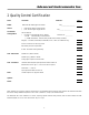
Advanced Instruments Inc. 2 Quality Control Certification Date: Customer: Order No.: Model GPR-1535 GB PPM Oxygen Transmitter Sensor ( ) GPR-12-100-M ppm Oxygen Sensor ( ) XLT-12-100-M ppm Oxygen Sensor Accessories Configuration Pass S/N ________________ S/N___________________ Owner’s Manual ( ) A-1161-L1 PCB Assembly, Main / Display Software Ver.
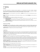
Advanced Instruments Inc. 3 Safety General This section summarizes the essential precautions applicable to the GPR-1500AIS ppm Oxygen Transmitter. Additional precautions specific to individual transmitter are contained in the following sections of this manual. To operate the transmitter safely and obtain maximum performance follow the basic guidelines outlined in this Owner’s Manual.
Advanced Instruments Inc. Maintenance Serviceability: Except for replacing the oxygen sensor, there are no parts inside the transmitter for the operator to service. Only trained personnel with the authorization of their supervisor should conduct maintenance. Oxygen Sensor: DO NOT open the sensor. The sensor contains a corrosive liquid electrolyte that could be harmful if touched or ingested, refer to the Material Safety Data Sheet contained in the Owner’s Manual appendix.
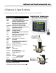
Advanced Instruments Inc. 4 Features & Specifications Specifications and pricing are subject to change without notice. See last page for current specifications.
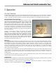
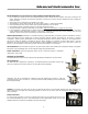
Advanced Instruments Inc. 5 Operation Principle of Operation The GPR-1535 GB incorporates a variety of ppm range advanced galvanic fuel cell type sensors. The transmitter is configured in a general purpose NEMA 4 rated enclosure and meets the intrinsic safety standards required for use in Class 1, Division 1, Groups C, D hazardous areas when operated in conjunction with the manufacturer’s recommended intrinsic safety barriers.
Advanced Instruments Inc. Installation Considerations Gas Sample Stream: Ensure the gas stream or composition of the controlled atmosphere of the application is consistent with the specifications and review the application conditions before initiating the installation. Consult the factory if necessary to ensure the sample is suitable for analysis.
Advanced Instruments Inc. Recommendations to avoid erroneous oxygen readings and damaging the sensor: ¾ Do not place your finger over the vent (it pressurizes the sensor) to test the flow indicator when gas is flowing to the sensor. Removing your finger (the restriction) generates a vacuum on the sensor and may damage the sensor (voiding the sensor warranty).
Advanced Instruments Inc. Connections – Optional Intrinsic Safety Barrier: See attached addendum Hazardous Area Operation: When used in conjunction with the optional intrinsic safety barriers, the design of the GPR-1535 GB meets recognized standards as intrinsically safe for operation in Class I, II, III; Division I, II; Groups C-G hazardous areas. Note: Locate the optional intrinsic safety barrier as close to the power source in the non-hazardous area as possible.
Advanced Instruments Inc. Span Gas Preparation Caution: Do not contaminate the span gas cylinder when connecting the regulator. Bleed the air filled regulator (faster and more reliable than simply flowing the span gas) before attempting the initial calibration of the instrument. Required components: ¾ Certified span gas cylinder with an oxygen concentration, balance nitrogen, approximating 80% of the full scale range above the intended measuring range.
Advanced Instruments Inc. Menu Navigation: The four (4) pushbuttons located on the front of the transmitter operate the micro-processor: ¾ green ENTER (select) ¾ yellow UP ARROW ¾ yellow DOWN ARROW ¾ blue MENU (escape) Main Menu: Access the MAIN MENU by pressing the MENU key: MAIN MENU AUTO SAMPLE MANUAL SAMPLE CALIBRATE 24.5 C 100 KPA Range Selection: The GPR-1500/1500D transmitter is equipped with five (5) standard measuring ranges (see specification) and provides users with a choice of sampling modes.
Advanced Instruments Inc. MAIN MENU MANUAL RANGE AUTO SAMPLE MANUAL SAMPLE CALIBRATE 24.5 C >>> 25% 1% 1000 PPM 100 PPM 10 PPM 100 KPA Advance the reverse shade cursor using the ARROW keys to highlight the desired RANGE. Press the ENTER key to select the highlighted menu option. The following display appears with the range selected and oxygen concentration of the sample gas: 3.3 PPM MANUAL SAMPLING 10 PPM RANGE 24.5 C 100 KPA The display will not shift automatically.
Advanced Instruments Inc. Calibration Single Point Calibration: As previously described the galvanic oxygen sensor generates an electrical current proportional to the oxygen concentration in the sample gas. In the absence of oxygen the sensor exhibits an absolute zero, e.g. the sensor does not generate a current output in the absence of oxygen. Given these linearity and absolute zero properties, single point calibration is possible.
Advanced Instruments Inc. Recommendation: Zero calibration, see Determining True Zero Offset below, is recommended only for online analyzers performing continuous analysis below 5% of the lowest most sensitive range available with a ppm analyzer, e.g. analysis below 0.5 ppm on the 10 ppm range, or below 0.1% (1000 ppm) with a percent analyzer.
Advanced Instruments Inc. 4. 5. 6. taped and securely tightened into the mating male quick disconnect fittings which mate with the female fittings on the transmitter Assure there are no restrictions in the gas line. Regulate pressure and control flow as described above. Assure the sample is adequately vented for optimum response and recovery – and safety. Air Calibration: 1. Install the sensor in the Sample Mode of the Glove Box Housing Assembly (right). 2.
Advanced Instruments Inc. PASSED CALIBRATION FAILED CALIBRATION OR Satisfying users that the zero offset is reasonably acceptable for their application can be accomplished much quicker. Unless the zero gas is contaminated or there is a significant leak in the sample connections, the transmitter should read less than 100 ppm oxygen within 5 minutes after being placed on zero gas. The maximum zero calibration adjustment permitted is 60% of the lowest full scale range available, which normally is 1 ppm.
Advanced Instruments Inc. MAIN MENU CALIBRATION AUTO SAMPLE MANUAL SAMPLE CALIBRATE 24.5 C >>> 100 KPA SPAN CALIBRATE ZERO CALIBRATE DEFAULT SPAN DEFAULT ZERO 24.5 C 100 KPA Manual Span The user must ascertain that the oxygen reading (actually the sensor’s signal output) has reached a stable value within the limits entered below before entering the span adjustment. Failure to do so will result in an error. Entering the span value – follow the menu layout in Appendix A.
Advanced Instruments Inc. MAIN MENU CALIBRATION AUTO SAMPLE MANUAL SAMPLE CALIBRATE 24.5 C 10. 11. 12. 13. 14. 15. 16. 17. 18. SPAN CALIBRATE ZERO CALIBRATE DEFAULT SPAN DEFAULT ZERO >>> 100 KPA 24.5 C 100 KPA Assure there are no restrictions in vent line. Regulate the pressure and control the flow rate as described above at 5-30 psig and a 2 SCFH flow rate. Allow the span gas to flow for 1-2 minutes to purge the air trapped in the span gas line.
Advanced Instruments Inc. 3.3 PPM AUTO SAMPLING 10 PPM RANGE 24.5 C 100 KPA 25. If the calibration is unsuccessful, return to the SAMPLING mode with span gas flowing through the transmitter, make sure the reading stabilizes and repeat the calibration before concluding the equipment is defective. 26. Before disconnecting the span gas line and connecting the sample gas line, restart if necessary the flow of sample gas and allow it to flow for 1-2 minutes to purge the air inside the line. 27.
Advanced Instruments Inc. 6 Maintenance Generally, cleaning the electrical contacts or replacing filter elements is the extent of the maintenance requirements of this transmitter. Sensor Replacement Periodically, the oxygen sensor will require replacement. The operating life is determined by a number of factors that are influenced by the user and therefore difficult to predict. The normal operating conditions and expected life of the standard sensor are defined in section 4 Specifications.
Advanced Instruments Inc.
Advanced Instruments Inc. Symptom Possible Cause Recommended Action Erratic O2 reading or No O2 reading Test sensor independent from transmitter Remove sensor from housing. Using a volt-meter set to uA output; apply the (+) lead to the outer ring of the sensor PCB and the (-) lead to the center circle to obtain the sensor’s output in air. Contact factory with result. Sensors without PCB use mV setting.
Advanced Instruments Inc. 9 Warranty The design and manufacture of the GPR-1535 GB PPM Oxygen Transmitter is performed under a certified Quality Assurance System that conforms to ISO 9001:2008 and incorporates state of the art materials and components for superior performance and minimal cost of ownership. Prior to shipment every analyzer is thoroughly tested by the manufacturer and documented in the form of a Quality Control Certification that is included in the Owner’s Manual accompanying every analyzer.
Advanced Instruments Inc. 10 MSDS – Material Safety Data Sheet Product Identification Product Name Oxygen Sensor Series - PSR, GPR, AII, XLT Synonyms Electrochemical Sensor, Galvanic Fuel Cell Manufacturer Analytical Industries Inc., 2855 Metropolitan Place, Pomona, CA 91767 USA Emergency Phone Number 909-392-6900 Preparation / Revision Date January 1, 1995 Notes Oxygen sensors are sealed, contain protective coverings and in normal conditions do not present a health hazard.
Advanced Instruments Inc. Reactivity Data Stability Stable Conditions Contributing to Instability None Incompatibility KOH = Avoid contact with strong acids or Acetic Acid = Avoid contact with strong bases Hazardous Decomposition Products KOH = None or Acetic Acid = Emits toxic fumes when heated Conditions to Avoid KOH = None or Acetic Acid = Heat Spill or Leak Steps if material is released Sensor is packaged in a sealed plastic bag, check the sensor inside for electrolyte leakage.