Advanced Instruments Inc. GPR-1500-A PPM Oxygen Transmitter Owner’s Manual 2855 Metropolitan Place, Pomona, California 91767 USA ♦ Tel: 909-392-6900, Fax: 909-392-3665, email: info@aii1.
Advanced Instruments, Inc Table of Contents Introduction 1 Quality Control Certification 2 Safety 3 Features & Specifications 4 Operation 5 Maintenance 6 Spare Parts 7 Troubleshooting 8 Warranty 9 Material Safety Data Sheets 10 Drawings A/R Explosion Proofing Electrical Connections Appendix A Correlating readings – LCD display to 4-20mA signal output Appendix B H2S Scrubber, Sample System, Media MSDS Appendix F Maintenance H2S Scrubber & Coalescing Filter Appendix G The ap
Advanced Instruments, Inc 1. Introduction Your new oxygen transmitter incorporates an advanced electrochemical sensor specific to oxygen along with state-of-the-art digital electronics designed to give you years of reliable precise oxygen measurements in a variety of industrial oxygen applications To obtain maximum performance from your new oxygen transmitter, please read and follow the guidelines provided in this Owner’s Manual.
Advanced Instruments, Inc 3. General Safety & Installation This section summarizes the essential precautions applicable to the GPR-1500IS Oxygen Transmitter. Additional precautions specific to individual transmitter are contained in the following sections of this manual. To operate the transmitter safely and obtain maximum performance follow the basic guidelines outlined in this Owner’s Manual.
Advanced Instruments, Inc 2.
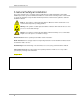
Advanced Instruments, Inc Maintenance Serviceability: Except for replacing the oxygen sensor, there are no parts inside the transmitter for the operator to service. Only trained personnel with the authorization of their supervisor should conduct maintenance. Oxygen Sensor: DO NOT open the sensor. The sensor contains a corrosive liquid electrolyte that could be harmful if touched or ingested, refer to the Material Safety Data Sheet contained in the Owner’s Manual appendix.
Advanced Instruments, Inc Materials: Assemble the necessary zero, sample and span gases and optional components such as valves, coalescing or particulate filters, and pumps as dictated by the application. Stainless steel tubing is essential for maintaining the integrity of the gas stream for low % or PPM O2 level analysis. Operating Temperature: The sample must be sufficiently cooled before it enters the analyzer and any optional components.
Advanced Instruments, Inc Caution: Do not place your finger over the vent (it pressurizes the sensor) to test the flow indicator when gas is flowing to the sensor. Removing your finger (the restriction) generates a vacuum on the sensor and may damage the sensor (voiding the sensor warranty). Application Pressure - Positive: A flow indicator with integral metering valve positioned upstream of the sensor is recommended for controlling the sample flow rate between 1-5 SCFH.
Advanced Instruments, Inc Power: Supply power to the transmitter only as rated by the specification or markings on the analyzer enclosure. The GPR-1500-A is a DC powered analyzer. The input power must be between 12-24 VDC. The wiring that connects the analyzer to the power source should be installed in accordance with recognized electrical standards. Ensure that the analyzer case is properly grounded and meets the requirements for area classification where the analyzer is installed.
Advanced Instruments, Inc 4.
Advanced Instruments, Inc 5. Operation Principle of Operation The GPR-1500-A Oxygen Transmitter incorporates advanced galvanic fuel cell type oxygen sensors. These sensors are very specific to oxygen and generate an electrical signal proportional to the amount of oxygen present in a gas stream. The selection of a particular type of sensor depends on the composition of the sample gas stream. Consult the factory for recommendation. The transmitter is configured with two integral electronic PCB.
Advanced Instruments, Inc Advanced Galvanic Sensor Technology All galvanic type sensors function on the same principle and are specific to oxygen.
Advanced Instruments, Inc Sample System The standard GPR-1500-A transmitter is supplied without a sample conditioning system thereby giving users the option of adding their own or purchasing a factory designed sample conditioning system, see section 2 QC Certification for optional equipment ordered. Whatever the choice, the sample must be properly conditioned before introducing it to the sensor to ensure an accurate measurement.
Advanced Instruments, Inc Example 1: As illustrated by Graph A, any error during a span adjustment at lower end of the scale, e.g., 20.9% (air) on a 100% full scale range, would be multiplied by a factor of 4.78 (100/20.9) when making measurements close to 100% O2. Conversely, an error during a span adjustment close to the top end of the range, e.g., at 100% is reduced proportionately for measurements of oxygen concentrations near the bottom end of the range.
Advanced Instruments, Inc Mounting the Transmitter The GPR-1500-A consists of metal enclosure and a sensor housing (without any optional sample conditioning system) and measures 7”H x 4”W x 4.5”D. This configuration is designed to be mounted directly to any flat vertical surface or bulkhead plate by using four (4) mounting studs at the back of front panel..
Advanced Instruments, Inc Gas Connections The GPR-1500-A with its standard flow through sensor housing configuration is designed for positive pressure samples and requires connections for incoming sample and outgoing vent lines. The user should adhere to the recommendation in terms of using the type of fittings, tubing, sample/span/zero gas pressure and sample flow rates. Failure to do so may cause permanent damage to the sensor.
Advanced Instruments, Inc The transmitter is equipped with a safety fuse rated at 1A 250 V (Manufacturer, Littelfuse, Part Number 3701100). When replacing the fuse, use a compatible fuse only ( described above). Power 12-24 VDC Fuse Transmitter Ground 1 A, F type Note: The male and female terminals snap together. Ensure that the male terminal is fully inserted and secured into the female terminal block.
Advanced Instruments, Inc Installing the Oxygen Sensor The GPR-1500-A Oxygen Transmitter is equipped with a SS sensor housing. This housing offers ease of replacement of sensor and at the same time prevents any air leakage into the system. The two sections of the sensor are held together by a metal clamp secured in place by easily accessed bolt. The integrity of the sensor housing has been tested at the factory prior to shipment and is fully operational from the shipping container.
Advanced Instruments, Inc 5. 6. Insert the sensor into the upper section of the sensor housing with gold contact plate facing towards two gold contact pins of the sensor housing By holding the sensor and the upper section of the sensor housing in your hand, allow 2-3 minutes for the analyzer to respond to the new sensor. The analyzer should display oxygen around 21% with factory default span setting (see below) Hold the sensor pressed against the contact pins inside the housing 7. 8. 9.
Advanced Instruments, Inc Span Gas Preparation Note: The GPR-1500-A transmitter can be calibrated by using ambient air. However, it can also be calibrated by using a certified span gas. Air calibration can be achieved right after installing the sensor in the housing. Subsequent calibration, where the sensor has been exposed to a sample gas, air calibration can be achieved by either removing the sensor from the sensor housing or by pushing the air through the sensor housing.
Advanced Instruments, Inc Establishing Power to Electronics Once the 12-24 VDC power is supplied, the digital display responds instantaneously. The transmitter performs several self-diagnostic system status checks termed as “START-UP TEST” as illustrated below: START-UP TEST ELECTRONICS – PASS TEMP SENSOR – PASS BAROMETRIC SENSOR – PASS REV. 2.14 After self diagnostic tests, the analyzer turns itself into the sampling mode.
Advanced Instruments, Inc Range Selection The GPR-1500-A transmitter is equipped with four (5) standard measuring ranges (see specification) and provides users with a choice of sampling modes. By accessing the MAIN MENU, users may select either the AUTO SAMPLING (ranging) or MANUAL SAMPLING (to lock on a single range) mode. Note: For calibration purposes, use of the AUTO SAMPLE mode is recommended. For example, calibration with ambient air (20.
Advanced Instruments, Inc MAIN MENU MANUAL RANGE >>> AUTO SAMPLE MANUAL SAMPLE CALIBRATION CONFIG ALARMS 25% 1% 1000 PPM 100 PPM 10 PPM BYPASS ALARMS Advance the reverse shade cursor using the ARROW keys to highlight the desired MANUAL RANGE. Press the ENTER key to select the highlighted menu option. The following display appears with the range selected and oxygen concentration of the sample gas: 0.
Advanced Instruments, Inc The transmitter is equipped with a “Zero Calibration” feature. However, as described below, zero calibration is recommended only when the application (or user) demands optimum accuracy of below 5% of the most sensitive or lowest range available on the transmitter. For example, if the user requires analysis of a sample gas below 0.5 PPM, a zero calibration is recommended.
Advanced Instruments, Inc Sensor PPM Fuel Cell Calibration at Install Air to .1% < 1 min Air to 100 PPM < 5 min Air to < 10PPM < 60 min In-service Calibration Similar Less than 45 min The above times assume the introduction of a zero gas (low level of oxygen in nitrogen) after span calibration. For optimum accuracy, the O2 concentration of a span gas should be approximate 50-90% of the full scale range of analysis or one range above the analysis range, e.g. 20.9% O2 on the 0-25% range.
Advanced Instruments, Inc Span Gas vs. Air Calibration The analyzer can be calibrated by using ambient air (20.9% O2 ) or a certified span gas. The only advantage of using a certified span gas for calibration is the fast recovery time to low PPM level after calibration. For example, if the analyzer is calibrated by using 8 PPM span gas, the analyzer will recover to within 0.1 PPM of the original reading within five minutes.
Advanced Instruments, Inc Both the Zero Calibrate and Span Calibrate functions result in the following displays: PASSED CALIBRATION OR FAILED CALIBRATION Default Zero The feature will eliminate any previous zero calibration adjustment and display the actual signal output of the sensor with the zero/sample gas. For example, assuming a zero gas is introduced, the display above 0.00 PPM will reflect an actual zero offset.
Advanced Instruments, Inc 3. Press the ENTER key to select the highlighted menu option and the following displays appear: MAIN MENU AUTO SAMPLE CALIBRATION >>> SPAN CALIBRATE MANUAL SAMPLE ZERO CALIBRATE CALIBRATION DEFAULT SPAN CONFIG ALARMS DEFAULT ZERO BYPASS ALARMS OUTPUT SPAN OUTPUT ZERO 4. 5. Advance the reverse shade cursor using the ARROW keys to highlight DEFAULT ZERO. Press the ENTER key to select the highlighted menu option and the following display appears: 100.
Advanced Instruments, Inc Span Calibration Procedure This procedure assumes a span gas under positive pressure and is recommended for a transmitter without an optional sampling pump, which if installed downstream of the sensor should be placed in the OFF position and disconnected so the vent is not restricted during calibration. To assure an accurate calibration, the temperature and pressure of the span gas must closely match with the sample gas.
Advanced Instruments, Inc The following displays appear: 000.00 % PRESS UP OR DOWN TO CHANGE VALUE ENTER TO SAVE MENU TO RETURN 0.55% >>> SPAN CLAIBRATION ENTER TO CALIBRATE MENU TO ABORT 11. Press the ENTER key to advance the underline cursor right or press the MENU key to advance the underline cursor left to reach to the desired digit of the alarm value. 12. Repeat until the complete span value has been entered. 13. Press the ENTER key to accept SPAN CALIBRATION.
Advanced Instruments, Inc MAIN MENU AUTO SAMPLE CALIBRATION >>> SPAN CALIBRATE MANUAL SAMPLE ZERO CALIBRATE CALIBRATION DEFAULT SPAN CONFIG ALARMS DEFAULT ZERO BYPASS ALARMS OUTPUT SPAN OUTPUT ZERO 4. Advance the reverse shade cursor using the ARROW keys to highlight DEFAULT SPAN. 5. Press the ENTER key to select the highlighted menu option. The following displays appear and after 3 seconds the system returns to the SAMPLING mode: 3.
Advanced Instruments, Inc 100.0 OUTPUT SPAN OFFSET PRESS UP OR DOWN TO CHANGE VALUE ENTER TO SAVE MENU TO RETURN The default setting of 100 illustrates no adjustment to the analog output signal. Compute the adjustment value as described in Appendix B or consult the factory. The true adjustment value must be determined empirically by trial and error. Adjust the initial value to above 100 to increase the 20 mA analog signal value or decrease it below 100 to decrease the 20 mA analog signal. 6.
Advanced Instruments, Inc Sampling GPR-1500-A Oxygen Transmitter requires a positive pressure to flow the sample gas across the sensor to measure the oxygen concentration in a sample gas. If a positive pressure sample not available, see Pressure & Flow section. Procedure Following calibration, the transmitter returns to the SAMPLE mode. From the Sample Mode, 1. Select the desired sampling mode - auto or if manual, the range that provides maximum resolution – as described above. 2.
Advanced Instruments, Inc 6. Maintenance Generally, cleaning the electrical contacts inside of the upper section of the sensor housing or replacing filter element of the coalescing filter is the extent of the maintenance requirements of this transmitter. Serviceability: Except for replacing the oxygen sensor, there are no parts inside the transmitter for the operator to service. Only trained personnel with the authorization of their supervisor should conduct maintenance. 7.
Advanced Instruments, Inc 8.
Advanced Instruments, Inc Symptom Possible Cause Recommended Action Response time slow Air leak, dead legs, distance of sample line, low flow rate, volume of optional filters and scrubbers Leak test (above), reduce dead volume or increase flow rate O2 reading doesn’t agree to expected O2 values Pressure and temperature of the sample is different than span gas Abnormality in gas Calibrate the transmitter (calibrate at pressure and temperature of sample) Qualify the gas (use a portable analyzer as a
Advanced Instruments, Inc or No O2 reading accompanied by electrolyte leakage suddenly removing the restriction draws a vacuum on the sensor or partially opened valves upstream of the transmitter when using a pump downstream of the transmitter to draw sample from a process at atmospheric pressure or under a slight vacuum. Placing a vacuum on the sensor in excess 10” of water column is strongly discouraged.
Advanced Instruments, Inc 9. Warranty The design and manufacture of GPR Series oxygen transmitters/analyzers, monitors and oxygen sensors are performed under a certified Quality Assurance System that conforms to established standards and incorporates state of the art materials and components for superior performance and minimal cost of ownership.
Advanced Instruments, Inc Be sure to pack the analyzer securely. Include your name, address, telephone number, and a description of the operating problem. After repairing or, at our option, replacing your Advanced Instruments Inc. analyzer, we will ship it to you at no cost for parts and labor. 10. MSDS – Material Safety Data Sheet Product Identification Product Name Oxygen Sensor Series - PSR, GPR, AII, XLT Synonyms Electrochemical Sensor, Galvanic Fuel Cell Manufacturer Advanced Instruments Inc.
Advanced Instruments, Inc Flammable Limits Not flammable Extinguishing Method Not applicable Special Fire Fighting Procedures Not applicable Unusual Fire and Explosion Hazards Not applicable Reactivity Data Stability Stable Conditions Contributing to Instability None Incompatibility KOH = Avoid contact with strong acids or Acetic Acid = Avoid contact with strong bases Hazardous Decomposition Products KOH = None or Acetic Acid = Emits toxic fumes when heated Conditions to Avoid KOH = None o
Advanced Instruments, Inc Special Precautions Precautions Transportation 41 Do not remove the sensor’s protective Teflon and PCB coverings. Do not probe the sensor with sharp objects. Wash hands thoroughly after handling. Avoid contact with eyes, skin and clothing. Empty sensor body may contain hazardous residue.
Advanced Instruments, Inc Appendix A Electrical connections require an approved explosion proof sealing fitting and packing around wires and cables (for incoming power for the analyzer electronics and 4-20mA signal output) coming into and out of the explosion proof enclosure that houses the power supply/signal output PCB. Full compliance with hazardous area electrical code requires the user to supply glands, fittings and/or conduit commensurate with the level of protection or classification desired.
Advanced Instruments, Inc Do not get into eyes or on skin – if cement touches eyes or skin, flush with water for 15 minutes. Large amounts on skin when hardening may cause skin burn. Use adequate ventilation.
Advanced Instruments, Inc Appendix B Matching - LCD Display with 4-20mA Output In rare instances the 4-20mA signal output may not agree with the reading displayed on the LCD. The Output Zero and Output Span features enable the user to adjust the 4mA and 20 mA signal output matching with the reading displayed by the LCD. For optimum accuracy make two separate adjustments as follows: 1. OUTPUT ZERO feature: To adjust the 4mA signal output and requires zero gas. 2.
Advanced Instruments, Inc Advance the reverse shade cursor using the ARROW keys to highlight CALIBRATION. Press the ENTER key to select the highlighted menu option. The following displays appear: MAIN MENU AUTO SAMPLE CALIBRATION >>> SPAN CALIBRATE MANUAL SAMPLE ZERO CALIBRATE CALIBRATION DEFAULT SPAN DEFAULT ZERO OUTPUT SPAN OUTPUT ZERO Advance the reverse shade cursor using the ARROW keys to highlight DEFAULT ZERO. Press the ENTER key to select the highlighted menu option.
Advanced Instruments, Inc Advance the reverse shade cursor using the ARROW keys to highlight CALIBRATION. Press the ENTER key to select the highlighted menu option. The following displays appear: MAIN MENU AUTO SAMPLE CALIBRATION >>> SPAN CALIBRATE MANUAL SAMPLE ZERO CALIBRATE CALIBRATION DEFAULT SPAN DEFAULT ZERO OUTPUT SPAN OUTPUT ZERO Advance the reverse shade cursor using the ARROW keys to highlight OUTPUT SPAN. Press the ENTER key to select the highlighted menu option.
Advanced Instruments, Inc 47
Advanced Instruments, Inc 48
Advanced Instruments, Inc 49
Advanced Instruments, Inc Appendix G Maintenance – H2S Scrubber Servicing any of the H2S scrubbers will depend on several factors as illustrated in Appendix F and include: the (average) H2S concentration, volume of scrubber media and flow rate through the scrubber (often times maximizing the service life means longer system response time) see Appendix F. Required equipment: 1. 2x 7/16” open end wrenches 2. 1x 9/16” open end wrench 3.
Advanced Instruments, Inc The filter element screws into the head section, carefully turn it counter clockwise and remove it from the head. Using the damp cloth, clean the inside of the bowl and the o-ring before reassembling – apply a very thin coat of lubricant to the o-ring. Reverse the above steps to re-assemble the filter.