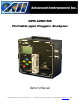
GPR-1200 MS Portable ppm Oxygen Analyzer Owner’s Manual 2855 Metropolitan Place, Pomona, CA 91767 USA ♦ Tel: 909-392-6900, Fax: 909-392-3665, e-mail: info@aii1.com, www.aii1.
Table of Contents Introduction 1 2 3 4 5 6 7 8 9 10 Quality Control Certification Safety Specifications Operation Maintenance Spare Parts Troubleshooting Warranty Material Safety Data Sheets Appendix C – Pump Options 1 Introduction Your new portable oxygen analyzer incorporates an advanced electrochemical sensor specific to oxygen along with state-of-the-art digital electronics designed to give you years of reliable precise oxygen measurements in variety of industrial oxygen applications.
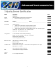
2 Quality Control Certification Date: Customer: Order No.: Pass Model GPR-1200 MSMS Portable ppm Oxygen Analyzer Sensor ( ) GPR-12-2000MS ppm Oxygen Sensor Serial Nos. Analyzer_________________________ Sensor _____________________________ Accessories Owner’s Manual ( ) PWRS-1002 9VDC Battery Charger/Adapter 110VAC ( ) PWRS-1003 9VDC Battery Charger/Adapter 220VAC ( ) PWRS-1008 9VDC Battery Charger/Adapter 12VDC Auto Cigarette Lighter CONN-1034 Plug Mini Phone .141 dia.
3 Safety General This section summarizes the essential precautions applicable to the GPR-1200 MS Series Portable ppm Oxygen Analyzer. Additional precautions specific to individual analyzer are contained in the following sections of this manual. To operate the analyzer safely and obtain maximum performance follow the basic guidelines outlined in this Owner’s Manual. Caution: This symbol is used throughout the Owner’s Manual to CAUTION and alert the user to recommended safety and/or operating guidelines.
Maintenance Serviceability: Except for replacing the oxygen sensor, there are no parts inside the analyzer for the operator to service. Only trained personnel with the authorization of their supervisor should conduct maintenance. Oxygen Sensor: DO NOT open the sensor. The sensor contains a corrosive liquid electrolyte that could be harmful if touched or ingested, refer to the Material Safety Data Sheet contained in the Owner’s Manual appendix.
4 Specifications * Accuracy: < 1% of FS range under constant conditions Analysis: 0-1 ppm, 0-10, 0-100, 0-1000 ppm FS ranges; auto-ranging or manually lock on single range Application: Analyze oxygen concentrations from 10 ppb to 1000 ppm in inert, hydrocarbon, helium, hydrogen and gas streams Approvals: CE, Intrinsic Safety (pending) Area Classification: Meets recognized intrinsic safety standards for use in Class 1, Division 1, Group C, D hazardous areas (see Options) Calibration: Certified gas
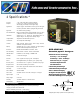
5 Operation Principle of Operation The GPR-1200 MS portable oxygen analyzer incorporates a proprietary Pico-Ion oxygen sensor. The analyzer is configured in a general purpose NEMA 4 rated enclosure and meets the intrinsic safety standards required for use in Class 1, Division 1, Groups A, B, C, D hazardous areas. Two integral sampling pump options are available – one that meets the intrinsic safety standards and a less expensive option for general purpose service.
Oxygen, the fuel for this electrochemical transducer, reacts chemically at the sensing electrode to produce an electrical current output proportional to the oxygen concentration in the gas phase. The sensor’s signal output is linear over all four ranges and remains virtually constant over its useful life. The sensor requires no maintenance or electrolyte addition and is easily and safely replaced at the end of its useful life.
Pressure & Flow All electrochemical oxygen sensors respond to partial pressure changes in oxygen. The inlet pressure must always be higher than the pressure at the outlet vent which is normally at atmospheric pressure. The sensor is exposed to sample gas that must flow or be drawn through the analyzer’s internal sample system. Flow rates of 1-5 SCFH cause no appreciable change in the oxygen reading.
The sample system may include optional additional components such as a 3-way sample/span valve, a pressure regulator, coiled metal tubing (samples must be cooled to at least 35-40º C for continuous use), coalescing filters, scrubbers, 3-way sample/return valve, backpressure regulator, etc. Note: The standard sample system is designed for positive pressure applications as described below under the Installation section.
Calibration & Accuracy Single Point Calibration: As previously described the galvanic oxygen sensor generates an electrical current sensor exhibiting an absolute zero, e.g. the sensor does not generate a current output in the absence of oxygen. Given these linearity and absolute zero properties, single point calibration is possible. Pressure: Because sensors are sensitive to the partial pressure of oxygen in the sample gas their output is a function of the number of molecules of oxygen 'per unit volume'.
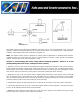
Example: As illustrated by Graph A any error, play in the multi-turn span pot or the temperature compensation circuit, during a span adjustment at 20.9% (air) of full scale range would be multiplied by a factor of 4.78 (100/20.9) if used for measurements of 95-100% oxygen concentrations. Conversely, an error during a span adjustment at 100% of full scale range is reduced proportionately for measurements of lower oxygen concentrations.
Mounting the Analyzer: Normally mounting a portable analyzer is not a consideration. However, The analyzer enclosure is cast with four (4) holes in the bottom section specifically intended for wall mounting. The GPR-1200MS analyzer can operate continuously when connected to AC power using the appropriate charging adapter. Gas Connection: The GPR-1200MS flow through configuration is designed for positive pressure samples and requires connections to incoming sample and vent 1/8” diameter tube fittings.
Installing the Oxygen Sensor GPR-1200 MS Portable ppm Oxygen Analyzer is equipped with an integral oxygen sensor. They are fully operational from the shipping container with the oxygen sensor installed, tested and calibrated by the manufacturer prior to shipment. Should it be necessary to install the oxygen sensor – see section 6 Maintenance which covers replacing the oxygen sensor.
Establishing Power to the Electronics: Establish power to the analyzer electronics by pushing the red ON/OFF key. The digital display responds instantaneously. When power is applied, the analyzer performs several diagnostic system status checks termed “START-UP TEST” as illustrated below: START-UP TEST ELECTRONICS – PASS BATTERY – PASS TEMP SENSOR – PASS BARO – N/A REV X.
Range Selection: The GPR-1200 MS analyzer is equipped with five (5) standard measuring ranges (see specification) and provides users with a choice of sampling modes. By accessing the MAIN MENU, users may select either the AUTO SAMPLING (ranging) or MANUAL SAMPLING (select one fixed range) mode. Note: For calibration purposes, use of the AUTO SAMPLE mode is recommended.
The following display(s) appear depending on the range selected and oxygen concentration of the sample gas: 0.000 PPM 0.000 PPM OR MANUAL SAMPLING 1 PPM RANGE OVERRANGE AUTO SAMPLING 1 PPM RANGE 24.5 C 24.5 C 00.00 PPM 00.00 PPM OR MANUAL SAMPLING 10 PPM RANGE OVERRANGE AUTO SAMPLING 10 PPM RANGE 24.5 C 24.5 C 000.0 PPM 000.0 PPM OR MANUAL SAMPLING 100 PPM RANGE OVERRANGE AUTO SAMPLING 100 PPM RANGE 24.5 C 24.
Zero Calibration In theory, the oxygen sensor produces no signal output when exposed to an oxygen free sample gas.
Note: Satisfying users that the zero offset is reasonably acceptable for their application can be accomplished much quicker. Unless the zero gas is contaminated or there is a significant leak in the sample connections, the analyzer should read less than 10 ppm oxygen within 5 minutes after being placed on zero gas. The maximum zero calibration adjustment permitted is 60% of the lowest full scale range available, which normally is 1 ppm. Thus the maximum zero calibration adjustment or zero offset is 0.
3. 4. 5. 6. 7. example, a span gas with an 80 ppm oxygen concentration with the balance nitrogen would dictate the use of the 0-100 ppm full scale range for calibration and a 0-1 ppm measuring range. Select as described above. Refer to Span Gas Preparation section above. Access the MAIN MENU by pressing the MENU key. Advance the reverse shade cursor to highlight AUTO SAMPLE with the ARROW keys. Press the ENTER key to select the highlighted menu option.
80.00 PPM 000.00 PPM PRESS UP OR DOWN TO CHANGE VALUE SELECT TO SAVE ESC TO RETURN >>> SPAN CALIBRATION ENTER TO CALIBRATE ESCAPE TO ABORT 24. Press the ARROW keys to enter the first digit of the span value. 25. Press the ENTER key to advance the underline cursor right or press the MENU key to advance the underline cursor left to change the next digit of the span value. 26. Repeat steps 20 and 21 until the complete span value has been entered. 27.
The sensor is exposed to sample gas that must flow or be drawn through the analyzer’s internal sample system. The sample system may include optional additional components such as a 3-way sample/span valve, a pressure regulator, coiled metal tubing (samples must be cooled to at least 35-40º C for continuous use), coalescing filters, scrubbers, 3-way sample/return valve, backpressure regulator, etc.
7. For sample gases under positive pressure the user must provide a means of regulating the inlet pressure between 5-30 psig and the flow of the sample gas between 1-5 SCFH, a flow rate of 2 SCHF is recommended. 8. For sample gases under atmospheric or slightly negative pressure an optional sampling pump is recommended to draw the sample into the analyzer. Generally, no pressure regulation or flow control device is involved. 9.
An LED indicator located on the front panel will light continuously during the CHARGE cycle. A second LED indicator located on the front panel provides a blinking 72 hour warning LOW BATT of the need to recharge the battery. Caution: Operating the analyzer beyond this 72 hour warning may permanently damage the battery. Standby The analyzer has no special storage requirements. The sensor should remain connected during storage periods. Store the analyzer with the power OFF.
7 Spare Parts Recommended spare parts for the GPR-1200 MS Series Portable Oxygen Analyzer: Item No. Description GPR-12-2000MS ppm Oxygen Sensor Other spare parts: Item No.
8 Troubleshooting Symptom Possible Cause Recommended Action Slow recovery At installation, defective sensor Replace sensor if recovery unacceptable or O2 reading fails to reach 10% of lowest range Leak test the entire sample system: Vary the flow rate, if the O2 reading changes inversely with the change in flow rate indicates an air leak - correct source of leak Air leak in sample system connection(s) High O2 reading after installing replacing sensor or High O2 reading Sampling Abnormality in zero
Symptom Possible Cause Recommended Action Erratic O2 reading or No O2 reading Test sensor independent from analyzer Remove sensor from housing. Using a volt-meter set to uA output; apply the (+) lead to the outer ring of the sensor PCB and the (-) lead to the center circle to obtain the sensor’s output in air. Contact factory with result. Sensors without PCB use mV setting.
9 Warranty The design and manufacture of our oxygen sensors and analyzers is performed under a certified Quality Assurance System that conforms to established standards and incorporates state of the art materials and components for superior performance and minimal cost of ownership. Prior to shipment every analyzer is thoroughly tested by the manufacturer and documented in the form of a Quality Control Certification that is included in the Owner’s Manual accompanying every analyzer.
10 MSDS – Material Safety Data Sheet Product Identification Product Name Oxygen Sensor Series - PSR, GPR, AII, XLT Synonyms Electrochemical Sensor, Galvanic Fuel Cell Manufacturer Analytical Industries Inc., 2855 Metropolitan Place, Pomona, CA 91767 USA Emergency Phone Number 909-392-6900 Preparation / Revision Date January 1, 1995 Notes Oxygen sensors are sealed, contain protective coverings and in normal conditions do not present a health hazard.
Reactivity Data Stability Stable Conditions Contributing to Instability None Incompatibility KOH = Avoid contact with strong acids or Acetic Acid = Avoid contact with strong bases Hazardous Decomposition Products KOH = None or Acetic Acid = Emits toxic fumes when heated Conditions to Avoid KOH = None or Acetic Acid = Heat Steps if material is released Sensor is packaged in a sealed plastic bag, check the sensor inside for electrolyte leakage.