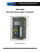
GPR-1000 Portable ppm Oxygen Analyzer Owner’s Manual 2855 Metropolitan Place, Pomona, CA 91767 USA ♦ Tel: 909-392-6900, Fax: 909-392-3665, e-mail: info@aii2.com, www.aii2.
Table of Contents Introduction 1 Quality Control Certification 2 Safety 3 Features & Specifications 4 Operation 5 Maintenance 6 Spare Parts 7 Troubleshooting 8 Warranty 9 Material Safety Data Sheets 10 1 Introduction Your new portable oxygen analyzer incorporates an advanced electrochemical sensor specific to oxygen along with state-of-the-art digital electronics designed to give you years of reliable precise oxygen measurements in variety of industrial oxygen applications.
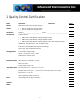
2 Quality Control Certification Date: Customer: Order No.: Model GPR-1000 Portable ppm Oxygen Analyzer Sensor ( ) GPR-12-100-M ppm Oxygen Sensor ( ) XLT-12-100-M ppm Oxygen Sensor Serial Nos. Analyzer_________________________ Sensor _____________________________ Accessories Owner’s Manual ( ) PWRS-1002 9VDC Battery Charger/Adapter 110VAC ( ) PWRS-1003 9VDC Battery Charger/Adapter 220VAC ( ) PWRS-1008 9VDC Battery Charger/Adapter 12VDC Auto Cigarette Lighter CONN-1034 Plug Mini Phone .
3 Safety General This section summarizes the essential precautions applicable to the GPR-1000 Series Portable ppm Oxygen Analyzer. Additional precautions specific to individual analyzer are contained in the following sections of this manual. To operate the analyzer safely and obtain maximum performance follow the basic guidelines outlined in this Owner’s Manual. Caution: This symbol is used throughout the Owner’s Manual to CAUTION and alert the user to recommended safety and/or operating guidelines.
Maintenance Serviceability: Except for replacing the oxygen sensor, there are no parts inside the analyzer for the operator to service. Only trained personnel with the authorization of their supervisor should conduct maintenance. Oxygen Sensor: DO NOT open the sensor. The sensor contains a corrosive liquid electrolyte that could be harmful if touched or ingested, refer to the Material Safety Data Sheet contained in the Owner’s Manual appendix.
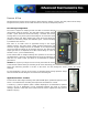
5 Operation Principle of Operation The GPR-1000 portable oxygen analyzer incorporates a variety of ppm range advanced galvanic fuel cell type sensors. The analyzer is configured in a general purpose NEMA 4 rated enclosure. An integral sampling pump options is available. Advanced Galvanic Sensor Technology: The sensors function on the same principle and are specific for oxygen.
Pressure & Flow All electrochemical oxygen sensors respond to partial pressure changes in oxygen. The inlet pressure must always be higher than the pressure at the outlet vent which is normally at atmospheric pressure. Flow Through Configuration: The sensor is exposed to sample gas that must flow or be drawn through metal tubing inside the analyzer.
Application Pressure - Atmospheric or Slightly Negative: For accurate ppm range oxygen measurements, an optional external sampling pump should be positioned downstream of the sensor to draw the sample from the process, by the sensor and out to atmosphere. A flow meter is generally not necessary to obtain the recommended flow rate with most sampling pumps, if the analyzer is equipped with a flow meter make sure the valve is completely open to avoid drawing a vacuum on the sensor.
Calibration & Accuracy Single Point Calibration: As previously described the galvanic oxygen sensor generates an electrical current sensor exhibiting an absolute zero, e.g. the sensor does not generate a current output in the absence of oxygen. Given these linearity and absolute zero properties, single point calibration is possible. Pressure: Because sensors are sensitive to the partial pressure of oxygen in the sample gas their output is a function of the number of molecules of oxygen 'per unit volume'.
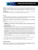
Example: As illustrated by Graph A any error, play in the multi-turn span pot or the temperature compensation circuit, during a span adjustment at 20.9% (air) of full scale range would be multiplied by a factor of 4.78 (100/20.9) if used for measurements of 95-100% oxygen concentrations. Conversely, an error during a span adjustment at 100% of full scale range is reduced proportionately for measurements of lower oxygen concentrations.
Gas Connections: The GPR-1000 flow through configuration is designed for positive pressure samples and requires connections to incoming sample and vent female quick disconnect fittings. The user is responsible for making provision for introducing gases for calibration purposes. Flow rates of 1-5 SCFH cause no appreciable change in the oxygen reading.
Output connection: The analyzer provides a 0-1V full scale with negative ground signal output for external recording devices. Procedure: 1. Connect the lead wires from the external recording device to the male phone plug supplied with analyzer. (Note: Connect the positive lead to the center terminal of the male phone plug.) 2. Insert the male phone plug into the integral female OUTPUT jack located on the side of the enclosure.
Establishing Power to the Electronics: Establish power to the analyzer electronics by pushing the red ON/OFF key. The digital display responds instantaneously. When power is applied, the analyzer performs several diagnostic system status checks termed “START-UP TEST” as illustrated below: START-UP TEST ELECTRONICS – PASS BATTERY – PASS TEMP SENSOR – PASS BARO – N/A REV. 1.
Main Menu: Access the MAIN MENU by pressing the MENU key: MAIN MENU AUTO SAMPLE MANUAL SAMPLE SPAN CALIBRATE ZERO CALIBRATE DEFAULT SPAN DEFAULT ZERO Range Selection: The GPR-1000 analyzer is equipped with five (5) standard measuring ranges (see specification) and provides users with a choice of sampling modes. By accessing the MAIN MENU, users may select either the AUTO SAMPLING (ranging) or MANUAL SAMPLING (to lock on a single range) mode.
For example, if the analyzer is reading 1% on the 0-10% range and an upset occurs, the display will shift to the 025% range when the oxygen reading exceeds 9.9%. Conversely, once the upset condition is corrected, the display will shift back to the 0-10% range when the oxygen reading drops to 8.5%. Procedure - Manual Sampling: 1. Access the MAIN MENU by pressing the MENU key. 2. Advance the reverse shade cursor to highlight MANUAL SAMPLE. 3. Press the ENTER key to select the highlighted menu option. 4.
0.000 PPM MANUAL SAMPLING 1000 PPM RANGE 0.000 PPM OVERRANGE AUTO SAMPLING 1000 PPM RANGE OR 24.5 C 24.5 C 0.000 % MANUAL SAMPLING 1% RANGE 0.000 % OVERRANGE AUTO SAMPLING 1% RANGE OR 24.5 C 24.5 C 00.00 % MANUAL SAMPLING 25% RANGE 00.00 % OVERRANGE AUTO SAMPLING 25% RANGE OR 24.5 C 24.5 C The display will not shift automatically.
Zero Calibration In theory, the oxygen sensor produces no signal output when exposed to an oxygen free sample gas.
Both the Zero Calibrate and Span Calibrate functions result in the following displays: PASSED CALIBRATION OR FAILED CALIBRATION Satisfying users that the zero offset is reasonably acceptable for their application can be accomplished much quicker. Unless the zero gas is contaminated or there is a significant leak in the sample connections, the analyzer should read less than 100 ppm oxygen within 5 minutes after being placed on zero gas.
Manual Span The user must ascertain that the oxygen reading (actually the sensor’s signal output) has reached a stable value within the limits entered below before entering the span adjustment. Failure to do so will result in an error. Entering the span value – follow the menu layout in Appendix A. Preparation - Required components: Refer to Installing Span Gas section above. 1.
5. Assure there are no restrictions in the span gas line. 6. Assure the male fitting designated for the vent is installed and the vent is open. 7. Regulate the pressure and control the flow rate as described above, 5-30 psig and 2 SCFH flow rate. 8. Allow the span gas to flow for 1-2 minutes to purge the air trapped in the span gas line. 9. Disconnect the sample gas line and install the purged span gas line. 10.
. Both the Zero Calibrate and Span Calibrate functions result in the following displays: PASSED CALIBRATION OR FAILED CALIBRATION 22. The analyzer returns to the AUTO SAMPLING mode after 30 seconds. 23. Before disconnecting the span gas line and connecting the sample gas line, restart if necessary the flow of sample gas and allow it to flow for 1-2 minutes to purge the air inside the line. 24. Disconnect the span gas line and replace it with the purged sample gas line. 25.
8. Caution: If the analyzer is equipped with an optional sampling pump and is intended for use in both positive and atmospheric/slightly negative pressure applications where a flow meter valve is involved – ensure the valve is completely open when operating the sampling pump. 9. Assure the sample is adequately vented for optimum response and recovery – and safety. 10. Allow the oxygen reading to stabilize for approximately 10 minutes at each sample point.
Standby ¾ The analyzer has no special storage requirements. ¾ The sensor should remain connected during storage periods. ¾ Store the analyzer with the power OFF. ¾ If storing for an extended period of time, charge before operating.
6 Maintenance Generally, cleaning the electrical contacts or replacing filter elements is the extent of the maintenance requirements of this analyzer. Sensor Replacement Periodically, the oxygen sensor will require replacement. The operating life is determined by a number of factors that are influenced by the user and therefore difficult to predict. The Features & Specifications define the normal operating conditions and expected life of the standard sensor utilized by the GPR-2000 Series analyzer.
7 Spare Parts Recommended spare parts for the GPR-1000 Series Portable Oxygen Analyzer: Item No. Description GPR-12-100-M ppm Oxygen Sensor XLT-12-100-M ppm Oxygen Sensor Other spare parts: Item No.
8 Troubleshooting Symptom Slow recovery High O2 reading after installing or replacing sensor High O2 reading Sampling Response time slow Possible Cause Recommended Action At installation, defective sensor Replace sensor if recovery unacceptable or O2 reading fails to reach 10% of lowest range Air leak in sample system connection(s) Leak test the entire sample system: Vary the flow rate, if the O2 reading changes inversely with the change in flow rate indicates an air leak - correct source of leak
Symptom Possible Cause Recommended Action O2 reading doesn’t agree to expected O2 values Pressure and temperature of the sample is different than span gas Calibrate the analyzer (calibrate at pressure and temperature of sample) Abnormality in gas Qualify the gas (use a portable analyzer) Erratic O2 reading or No O2 reading Test sensor independent from analyzer Remove sensor from housing.
Symptom Erratic O2 reading or Negative O2 reading or No O2 reading possibly accompanied by electrolyte leakage Possible Cause Recommended Action Pressurizing the sensor by flowing gas to the sensor with: the vent restricted or SHUT OFF valve closed and suddenly removing the restriction draws a vacuum on the sensor or partially opening the valves upstream of the analyzer when using a pump downstream of the analyzer to draw sample from a process at atmospheric pressure or a slight vacuum Zero the analyzer
9 Warranty The design and manufacture of AII 3000 Series Oxygen Analyzers and Monitors, and, oxygen sensors are performed under a certified Quality Assurance System that conforms to established standards and incorporates state of the art materials and components for superior performance and minimal cost of ownership.
10 MSDS – Material Safety Data Sheet Product Identification Product Name Oxygen Sensor Series - PSR, GPR, AII, XLT Synonyms Electrochemical Sensor, Galvanic Fuel Cell Manufacturer Analytical Industries Inc., 2855 Metropolitan Place, Pomona, CA 91767 USA Emergency Phone Number 909-392-6900 Preparation / Revision Date January 1, 1995 Notes Oxygen sensors are sealed, contain protective coverings and in normal conditions do not present a health hazard.
Reactivity Data Stability Stable Conditions Contributing to Instability None Incompatibility KOH = Avoid contact with strong acids or Acetic Acid = Avoid contact with strong bases Hazardous Decomposition Products KOH = None or Acetic Acid = Emits toxic fumes when heated Conditions to Avoid KOH = None or Acetic Acid = Heat Spill or Leak Steps if material is released Sensor is packaged in a sealed plastic bag, check the sensor inside for electrolyte leakage.