
Product Manual


5
Designed and manufactured by: ANALYTIC SYSTEMS WARE (1993) LTD.
8128 River Way
Delta, BC V4G 1K5 Canada
p. 604.946.9981 f. 604.946.9983
tf. 800.668.3884 US/Canada
www.analyticsystems.com analyticinfo@analyticsystems.com Revised September 2014
Allow at least 1 inch of clearance all around the case for cooling. The best mounting congu-
ration is to mount the unit on a vertical surface oriented as shown. Use #10 screws of the
appropriate type for the mounting surface to securely mount the unit.
The case has 500 volts of isolation from both the input and output, so it may be mounted on
any surface without fear of electrolysis or ground fault.
The unit is supplied with input leads 1 meter long of #10 AWG wire. This should be adequate
to connect to a breaker panel or other source of power. If you need to extend the wires, use
at least #10 AWG wire and solder and heat shrink the connection to protect the joint. Connect
the Red wire to Positive, and the Black wire to Negative. If a 12V unit is being run from a
24V battery system, use a 40 amp panel breaker to feed power to it, and use a 25 amp panel
breaker for a 32V battery system. Use a 40 amp breaker to feed power to a 24V unit. Each
VTC600 Series Voltage Converter should have its own breaker in the panel.
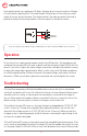
To reduce radio noise to the absolute minimum, it may be necessary to bond the case to the
vessel ground. To do this, remove one the nuts on the grounding stud located next to the
input wires. Then place a #6 ring terminal with a ground wire crimped to it onto the stud, and
replace the nut.
Refer to the manufacturers specications and add up the current ratings for each device to
be connected to the unit. Make sure that the total load does not exceed the continuous rating
of the unit (50 Amps -12 or 35 Amps -24). The devices may be wired directly to the output
terminals of the unit, or the unit can be wired to a distribution panel if it is more convenient. If
the unit is wired to a distribution panel, run wires from each terminal to the panel.
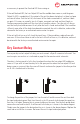
#10 MOUNTING HOLE (X4)
ON/OFF
INPUT POWER
RED
BLACK
OUTPUT
ADJUST
OVERLOAD
OVERTEMP
LOW OUTPUT
LOW INPUT
POWER
OUTPUT 1
OUTPUT 2
GROUNDING STUD
TO
REMOTE
INPUT FUSE AGC 25
INPUT FUSE AGC 25