
Product Manual


7
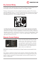
Dry Contact Relay
Remote Control Option
To use the dry contact output fail relay you must connect a 9-pin D connector to the unit. You
must use pins one and six as indicated in the remote control diagram on page 7.
The relay is factory preset to fail in the closed position when the converter is OFF or the low
output LED and buzzer come on. If you wish to have the relay fail in the open position when the
low output LED and buzzer come on, you must take the cover off the unit and move the jumper
to the other position on J13. J13 is located next to the relay.
To change the position of the jumper, rst turn the unit off and disconnect the unit from both
the I/P power and O/P load. Next, turn the unit on for 30 seconds to discharge the capacitors,
and then turn it off again. Turn the unit upside down and remove the four screws. Remove the
base plate and locate J13. It will be next to the relay as is shown in the above diagram. Simply
move the jumper to the desired position as is shown in the above diagram. Replace the base
plate and re-install the four screws.
This connector is located on the side of the unit. Important: To prevent the possibility of High
Voltage Electrical Shock, do not power up the Converter unless all wiring from the unit to the
remote is securely connected. Do not remove the dust cover from the DB-9 connector if the
remote is not being used.
IMPORTANT: This remote is to be used only on Voltage Converters manufactured by Analytic
Systems.
A remote control panel may be connected to the voltage
converter using a 9-pin D-connector, which attaches
to the front panel of the battery charger. The remote
control panel and D connector are part of the remote
control option. The remote control panel allows the unit
to be operated remotely as well as duplicating all the
diagnostic indicators and audible alarm.