
Product Manual


6
Installation
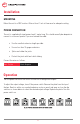
MOUNTING
Mount the unit in a DRY location. Allow at least 1 inch of clearance for adequate cooling.
POWER CONNECTION
The unit is supplied with input power leads 1 meter long. This should normally be adequate to
connect to a source of power. If you must extend the cable:
• Use the smallest extension length possible.
• Use no less than 10 gauge conductors.
• Splice and solder the joints.
• Protect the joints with heat shrink tubing.
Connect the wires as follows:
Operation
Turn the power switch on the front of the unit on to energize the outputs.
To adjust the output voltage, turn off the power switch. Remove the plate from the top of
the box. Reach in with a non-conductive device such as a pencil and open or close the dip
switches as shown below to select the desired output voltage. Replace the plate. Turn the
power switch on.
Red - Positive Black- Negative