
Product Manual


5
Operation
With the power turned off wire the converter as described above. Then, turn on the power.
Installation
MOUNTING
Mount the unit in a DRY location. Allow at least 1 inch of clearance around the heat sink ns
for adequate cooling.
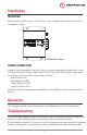
POWER CONNECTION
A terminal strip is provided at one end of the unit for connecting input and output leads. For the
VTC140 use #12 AWG wring or larger and for the VTC240 use #10 AWG wiring or larger. Keep
the wiring as short as possible. Connect leads as follows:
Input Positive to IN +
Input Negative to GND -
Output Negative to GND -
Output Positive to OUT +
Ensure that the total average load connected does not exceed the continuous current rating of
the unit.
VTC140-24-12 is shown
Troubleshooting
If the current demanded by the devices connected to the unit exceed the maximum output current
rating, the output voltage will drop to maintain the current at the maximum level.
If the fuse blows whenever it is turned on, check that the power leads are connected to the battery
with the correct polarity; if they are then the unit is damaged and must be returned for repair.