
Product Manual


6
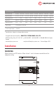
POWER CONNECTION
The ON/OFF switch must be in the OFF position before
connecting or disconnecting power to the unit!
A terminal strip is provided at one end of the unit for connecting input and output leads.
Connect leads as follows:
Input Positive to IN + Output Negative to OUT -
Input Negative to IN - Output Positive to OUT +
Ensure that the total average load connected does not exceed the continuous current rating of
the unit.
CONNECTIONS
Turn the switch on the side of the unit on to energize the outputs.
Troubleshooting
If the current demanded by the devices connected to the unit exceed the maximum output current rating, the output
voltage will drop to maintain the current at the maximum level.
If the fuse blows whenever it is turned on, check that the power leads are connected to the battery with the correct
polarity; if they are then the unit is damaged and must be returned for repair.
Special Services & Options
Conformal Coating INCLUDED ON ALL UNITS UNLESS REQUESTED NOT TO as of April 1, 2014
Option “c” Ruggedization Package (EXTRA Conformal Coating and RTV Compound)
Option “v” Marine / Industrial Pkg (EXTRA Conformal dipping and RTV Compound)
Option “MS” Military Pkg
(incl. Wide Temp Components, Conformal Dipping and RTV Compound)
Option “w” Wide Temperature Operation (-40 to +55 C, incl)
Option “SM” High Voltage Protection on the DC Input Side
Option “d” Paralleling Diodes
Option “FI” Forklift Modi cations
Option “F” Open Frame - No chassis just heat sink bars (not for all products)
Special Input
There is no charge for nominal output voltages (ie. 12.0, 24.0, 48.0), but this
must be noted at the time of order (Contact Factory for details)
Special Output
Water tight options IP66, IPS67, IPS68