
Product Manual


7
Operation
Turn the switch on the top of the unit on to energize the outputs. The green ‘Output On’ indica-
tor light will glow to indicate the proper operation of the unit.
OUTPUT ADJUSTMENT
As shipped from the factory, the unit is preset to 13.6, 27.2, 36.3 or 54.4VDC. You may check
this voltage at the output terminals of the unit with a good digital voltmeter. If you wish to
adjust the output voltage, remove the cover plate (secured by 2 screws) to expose the output
adjust potentiometer. Reach in with a very small at blade screwdriver to rotate the potenti-
ometer. Clockwise increases the output voltage, and counter clockwise decreases it. When
you are done, replace the cover plate and securely tighten the screws.
METERS
A high quality digital meter can be added to the voltage converter (factory installed only).
The meter shows simultaneous voltage and current on either of the two output terminals. A
toggle switch permits selection between the output terminals. The meter features bright LED
readouts to permit easy monitoring from many feet or meters away.
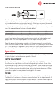
LOAD SHARE OPTION
The units may be congured for load sharing if they are equipped with the optional output
isolation diodes. To conrm that your unit has these diodes, use an ohmmeter to measure the
resistance between the two positive output terminals. If the diodes are present the terminals
will measure as not connected. If the diodes are NOT present, the terminals will measure as a
short circuit. Assuming the output isolation diodes are present, connect a one-foot piece of red
wire of the appropriate gauge (as shown in the table below)
to each positive output terminal. Connect all the positive wires to a distribution bus, or
connect them together. Then connect from the common point to the load using the correct
gauge of wire for the total output capability of all the supplies running in parallel.
Repeat this process for the negative terminals using the same gauges of wire, but black in
colour. These units should now load share. You can conrm this by watching the output amme-
ters. A slight difference is acceptable. If there is more than a slight difference, then increase
the output voltage of the unit that is reading low using the output adjust potentiometer.
Output Voltage (Vdc) 12 24 32 48
Wire Gauge (AWG) #8 #10 #12 #14