
Product Manual


7
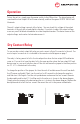
Operation
To turn the unit on, simply move the power switch to the ON position. The alarm buzzer will
sound and the Low Output LED will come on briey, and then the green OUTPUT ON LED will
illuminate.
The unit’s output voltage is preset at the factory. You may check this voltage at the output
terminals of the unit with a good digital voltmeter. If you wish to adjust the output voltage,
use a very small at blade screwdriver to rotate the potentiometer. Clockwise increases the
output voltage, and counter clockwise decreases it.
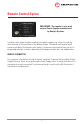
To use your dry contact output fail relay you must connect a 9-pin D connector to the unit. You
must use pins one and six as is indicated in the remote control diagram on page 7.
The relay is factory preset to fail in the closed position when the low output LED and buzzer
come on. If you wish to have the relay fail in the open position when the low output LED and
buzzer come on, you must take the cover off the unit and move the jumper to the other position
on J11. J11 is located next to the relay.
To change the position of the jumper, rst turn the unit off and disconnect the unit from both
the I/P power and load(s). Next, turn the unit on for 30 seconds to discharge the apacitors,
and then turn it 0off again. Turn the unit upside down and remove the four screws. Remove
the base plate and locate J11. It will be next to the relay as is shown in the above diagram.
Simply move the jumper to the desired position as is shown in the above diagram. Replace the
base plate and re-install the four screws. Reconnect the unit to the power and batteries.
Dry Contact Relay