
Product Manual


6
Installation
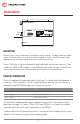
MOUNTING
Allow at least 1 inch of clearance all around the case for cooling. The best mounting congu-
ration is to mount the unit on a vertical surface oriented as shown. Use #10 screws of the
appropriate type for the mounting surface to securely mount the unit.
There is 1500 volts of isolation between the input and output, and the input and case. There
is 500 volts (1500V for 48V Output) of isolation between the output and case. Therefore, the
unit, may be mounted on any surface without fear of electrolysis or ground fault.
POWER CONNECTION
The unit is supplied with power leads about 3 feet long. This should normally be adequate to
connect to a source of power. If you must extend the power leads, be sure to use at least a
good quality (typeTEW) AWG 8 gauge wire. The wire colours are:
All connections should be made inside an appropriate junction box. The maximum current
draw from the supply is 4.9 amps (110Vac) or 2.5 amps (220Vac), so a 5 amp circuit breaker
should be used in the circuit panel to feed power to the PWS310.
To reduce radio noise to the absolute minimum, it may be necessary to bond the case to local
ground. For this purpose, a ground stud has been provided.
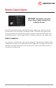
OUTPUT
FUSE
TO
REMOTE
OUTPUT TERMINAL
ON/OFF
INPUT POWER
110 VAC 220 VAC
Brown - AC Hot Brown - AC Hot / Phase 1
Blue - AC Neutral Blue - AC Neutral / Phase 2
Green - Ground Green/Yellow - Ground