INSTALLATION & OPERATION MANUAL PWS120 & PWS 240 Power Supplies An ISO9001 and AS9100 Registered Company Battery Chargers • Inverters • Power Supplies • Voltage Converters 8128 River Way, Delta B.C. V4G 1K5 Canada T. 604.946.9981 F. 604.946.9983 TF. 800.668.3884 (US/CANADA) www.analyticsystems.
Copyright (2005-2014) Analytic Systems Ware (1993) Ltd.
IMPORTANT & SAFETY INSTRUCTIONS SAVE THESE INSTRUCTIONS — This manual contains important safety and operating instructions for the converter. ALL POWER SUPPLIES 1. WARNING – Unless the label specifically states that the power supply may be used for battery charging, it must NOT be used for that purpose. 2. Do not expose power supply to rain or snow. 3. Use of an attachment not recommended or sold by the power supply manufacturer may result in a risk of fire, electric shock, or injury to persons. 4.
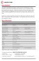
Introduction The PWS120 & PWS240 Power Supplies are MosFet based switchmode power supplies designed for high reliability, high efficiency and minimum size. Circuit innovations reduce output ripple to levels previously available only from bulky, inefficient linear power supplies. Current limiting and safe operating area circuitry protect the transistors. A crowbar circuit protects any devices powered by the unit from excessive voltage in the unlikely event of a failure.
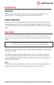
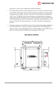
Installation MOUNTING Mount the unit in a DRY location. Allow at least 1 inch of clearance around the unit for adequate cooling. Do not block the ventilation slots on the sides of the unit. POWER CONNECTION Ensure the switch is in the OFF position. Connect the power cord to the power supply then connect the power cord to the AC source. Connect the output of the power supply to the DC load. The RED terminal is the positive output and the BLACK or WHITE terminal is the negative output.
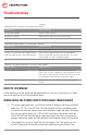
Troubleshooting (General) PROBLEM: ON/OFF switch does not illuminate when turned on. Probable Cause Suggested Remedy No AC power available. Check AC outlet for power. AC input fuse is blown. Replace the fuse with a fuse of the correct rating.
transceiver is in the transmit mode (high current consumption). • The antenna being too close to the equipment may cause a slowly oscillating buzzing carrier heard in the receiver. A loose coaxial connector or a broken or missing ground may aggravate this problem. Normally, these noises will be below the background or “band” noise. RF feedback from the transmitter may create instability in the power supply causing a poor sounding, raspy or unstable transmitted signal.
Intentional blank page 8
Intentional blank page 9
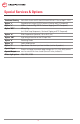
Special Services & Options Conformal Coating INCLUDED ON ALL UNITS UNLESS REQUESTED NOT TO as of April 1, 2014 Option “c” Ruggedization Package (EXTRA Conformal Coating and RTV Compound) Option “v” Marine / Industrial Pkg (EXTRA Conformal dipping and RTV Compound) Option “MS” Military Pkg (incl.
Limited Warranty 1. The equipment manufactured by Analytic Systems Ware (1993) Ltd. (the “Warrantor”) is warranted to be free from defects in workmanship and materials under normal use and service. 2. This warranty is in effect for: a. 3 Years from date of purchase by the end user for standard products offered in our catalog. b. 2 Years from date of manufacture for non-standard or OEM products c. 1 Year from date of manufacture for encapsulated products. 3.
An ISO9001 and AS9100 Registered Company Battery Chargers • Inverters • Power Supplies • Voltage Converters 8128 River Way, Delta B.C. V4G 1K5 Canada T. 604.946.9981 F. 604.946.9983 TF. 800.668.3884 (US/CANADA) www.analyticsystems.