
Product Manual


6
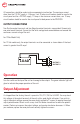
Operation
Output Adjustment
Turn the switch on the top of the unit on to energize the outputs. The green indicator light will
glow to indicate the proper operation of the unit.
As shipped from the factory, the unit is preset to 13.6, 27.2, 36.3 or 54.4VDC. You may check
this voltage at the output terminals of the unit with a good digital voltmeter. If you wish to
adjust the output voltage, remove the cover plate (secured by 2 screws) to expose the output
adjust potentiometer. Reach in with a very small at blade screwdriver to rotate the potenti-
ometer. Clockwise increases the output voltage, and counter clockwise decreases it. When
you are done, replace the cover plate and securely tighten the screws.
All connections should be made inside an appropriate junction box. The maximum current
draw from the 110 VAC supply is 14.6 amps, so a 20 amp circuit breaker should be used in the
circuit panel and for a 220 VAC supply, 7.3 amps is the maximum current draw, so a 10 amp
circuit breaker should be used in the circuit panel to feed power to the PWS1000.
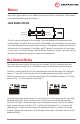
OUTPUT CONNECTIONS
Two Positive output terminals and two Negative output terminals are provided. Connect only
one wire to each terminal. Ensure that the total average load connected does not exceed the
continuous current rating of the unit.
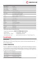
For 12Vdc Model Only!
For 12 Vdc models only, the output terminals must be connected as shown below if the load
current is greater than 50 amps!
OUTPUT 1
OUTPUT 2
LOAD