
IPSi3600 Manual


5
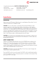
Installation
MOUNTING
Mount the unit in a DRY location. Mount the unit in a ventilated area. Allow at least 1 inch of
clearance around the unit for adequate cooling.
CAUTION: The case of the inverter is connected to AC Ground and AC Neutral to meet
regulatory requirements and to reduce the possibility of it generating any radio frequency
interference. The case must be bonded appropriately to the grounding system of the vehicle or
marine vessel. On a vehicle bond the case to the frame and on a marine vessel bond the case
to the hull. A grounding stud is provided on the front of the inverter for this purpose. To ensure
proper grounding, check the connection with an ohmmeter. The case is isolated from the DC
Input, so the DC power can be on a different ground from the AC output.
CAUTION: Do not mount the unit where explosive gases may accumulate as a slight arc may
occur when the power leads are connected, and in the unlikely event of a failure, sparks may
be generated inside the unit.
INPUT CONNECTION
Prepare a circuit breaker protected power source for the IPSi3600 Inverter, making sure the
breaker is OFF. Connect the input power to the DC IN terminal blocks using at least AWG2
stranded wire for -20 model and AWG4 for the -40 model . Connect the positive to the RED
terminal and the Negative to the BLACK terminal. The Inverter has Inrush Protection on the DC
input to reduce sparking during the connection process.
CAUTION: Do Not Reverse Connect the Input Wires. This will cause serious Damage to the
Inverter and will not be covered by Warranty.
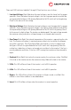
Press the ON/OFF switch to turn on the inverter. The ON/OFF switch should illuminate and the
Invert LED should come on Green. Once proper operation is conrmed, turn the inverter OFF by
pressing the ON/OFF switch again.
Designed and manufactured by: ANALYTIC SYSTEMS WARE (1993) LTD.
8128 River Way
Delta, BC V4G 1K5 Canada
p. 604.946.9981 f. 604.946.9983
tf. 800.668.3884 US/Canada
www.analyticsystems.com info@analyticsystems.com Revised February 2016