
Product Manual


10 11
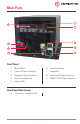
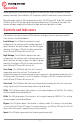
Remote Control Port
This port is intended to connect to an Analytic Systems Digital Remote Control, but can also
be used for as a remote ON/OFF switch, isolated RS232 communications terminal and dry
contact output fail indicator.
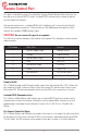
The remote control port is a standard RJ45 style “telephone jack“ connector with Analytic
Systems proprietary connections. The wire colors in the table below correspond to colors
found in any standard T-568B network cable.
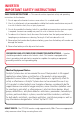
CAUTION: Do not connect this port to a computer!
This will cause serious damage to the Inverter and computer. This damage is not be covered
under warranty.
Pin Number Wire Color Function
1 White/Orange Stripe Remote ON/OFF
2 Orange Digital Ground
3 White/Green Stripe +12V Out
4 Blue RX RS232
5 White/Blue Stripe TX RS232
6 Green Gnd RS232
7 White/Brown Dry Contact Relay
8 Brown Dry Contact Relay
Remote On/Off
Pins 1 (White/Orange) and 2 (Orange) can be used to turn the Inverter ON or OFF. Connect the
pins together through a switch or relay to turn the Inverter OFF and disconnect them to turn
the Inverter ON. The front panel power switch must be ON for this connection to function.
Isolated RS232 Communications
Pins 4 (Blue), 5 (White/Blue) and 6 (Green) are an isolated RS232 port that can be used for
communication to/from the Inverter. Information on the standard data structure or custom
programming is available from the Analytic Systems. Pin 4 is RX, Pin 5 is TX and Pin 6 is
Return.
Dry Contact Output Fail Relay
Pins 7 (White/Brown) and 8 (Brown) are wired to the contacts of an output fail relay controlled
by the processor. The contacts will be CLOSED if the Inverter is operating normally and OPEN
if it has failed. An LED or buzzer can be wired to these pins to serve as a failure indicator.