
IBI Series Manual


8
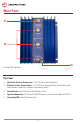
Ground Connection
The IBI uses a ground reference to operate its control circuitry which it reads through the
Ground Connection. To set up this connection:
1. Prepare an AWG18 wire with a #10 lug on one end.
2. Connect this end of the wire to Ground Point.
3. Connect the other end of the wire to the battery negative terminal or directly the engine
block. If the ground is properly connected, the Grounding LED will be illuminated.
Ignition (IGN) Connection
The Ignition (IGN) Connection is an optional connection. If you read a normal charging current
from your alternator to the battery banks after setting up the IBI then you do not need to use
this connection.
If there is no charging current after installing the IBI, you may need to set up the Ignition
Connection. Some alternators need to ‘see’ the battery voltage in order to begin charging.
The IBI applies battery voltage to the alternator through a diode isolation circuit using this
connection. To set up this connection:
1. Prepare an AWG18 gauge wire with a common 1/4” female quick connect on one end.
2. Connect this end of the wire to the Ignition (IGN) Connection.
3. Connect the other end of the wire the ignition switch of your vehicle. You may
alternatively connect this end to any other point that is live with battery voltage only
when the ignition is ON.
Output Connection
The output connection connects the battery isolator to the battery banks. To set up this
connection:
For each battery bank:
1. Prepare a cable with a 1/4” lug on one end (End A) . On the other end, attach a connector
suitable for the positive terminal of the battery bank (End B)
2. Connect End A to the Battery Positive Connection.
3. Connect End B to the positive terminal of the battery bank.
4. Connect the negative terminal of the battery bank to the ground.