
Product Manual


7
Operation
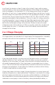
Prior to turning on the unit, you must decide on which charging prole, 2 or 3 stage charging,
to use. To help you decide, please see the following section entitled 2 or 3 Stage Charging to
determine the charging prole.
Once you have decided on the charging prole you must set the switch to the correct posi-
tion. To access the switch, remove the cover plate (secured by 2 screws). Set the switch to
the correct position as shown on the label. When you are done, replace the cover plate and
securely tighten the screws.
To turn the unit on, simply move the power switch to the ON position. The alarm buzzer will
sound and the Low Output LED will come on briey, and then the green OUTPUT ON LED will
illuminate.
When the unit is rst turned on, it will charge the batteries at maximum current and the
charging light will be on. After a period of time, which may be minutes to hours, the batter-
A ground stud is provided to bond the chassis to local ground to reduce or eliminate EMI.
OUTPUT CONNECTIONS
Two Positive output terminals and two Negative output terminals are provided. Connect only
one wire to each terminal. Ensure that the total average load connected to the batteries does
not exceed the continuous current rating of the unit.
To ensure spark free connections the power switch must be in the OFF position prior to making
the connections to the battery bank(s).
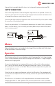
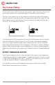
The unit may be hooked to 1 or 2 battery banks depending on the model. Hook up the battery
bank(s) as shown below. If you are hooking up 2 battery banks keep in mind that they MUST
share a common ground!
OUTPUT 1 OUTPUT 1
OUTPUT 2 OUTPUT 2
BATTERY
BANK #1
BATTERY
BANK #1
BATTERY
BANK #2
Meters
High quality digital meters can be added to the charger (factory installed only). Both outputs
can be monitored for current and voltage.