
Operating instructions


8
Troubleshooting
If the load exceeds the continuous rating for too long a period, the internal temperature sensor
will cause the unit to stop boosting the input voltage until the unit has cooled down. After the
unit has cooled down, normal operation will resume.
If the input voltage drops below the specied minimum input, the unit will sound the alarm.
If the output voltage drops below the specied minimum, the unit will sound the alarm.
If the current demanded by the devices connected to the unit exceed the maximum current
rating, the fuse will blow.
If the fuse blows with no load connected, check that the power leads are connected to the
battery with the correct polarity; if they are then the unit is damaged and must be returned for
repair.
Operation
Turn the power switch on the front of the unit on to energize the outputs.
If you wish to adjust the output voltage, rst attach a good digital voltmeter to the output
terminals to monitor the voltage. Next, remove the cover plate (secured by 2 screws) to
expose the output adjust potentiometer. Reach in with a very small at blade screwdriver
to rotate the potentiometer. Clockwise increases the output voltage, and counter clockwise
decreases it. When you are done, replace the cover plate and securely tighten the screws.
Remove the voltmeter from the output terminals.
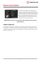
To use your dry contact output fail relay you must connect a 9-pin D connector to the unit.
You must use pins one and six as is indicated on page 8 in the remote connector diagram.
The relay is factory preset to fail in the closed position when the low output LED and buzzer
come on. If you wish to have the relay fail in the open position when the low output LED and
buzzer come on, you must take the cover off the unit and move the jumper to the other posi-
tion on J11. J11 is located next to the relay.
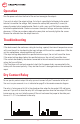
Dry Contact Relay